Mounting structure and electro optical device
a technology of mounting structure and electro optical device, which is applied in the direction of identification means, semiconductor/solid-state device details, instruments, etc., can solve the problems of increasing wiring resistance and not being able to avoid the reduction of width, and achieve good electrical connection
- Summary
- Abstract
- Description
- Claims
- Application Information
AI Technical Summary
Benefits of technology
Problems solved by technology
Method used
Image
Examples
first embodiment 1
Whole Structure
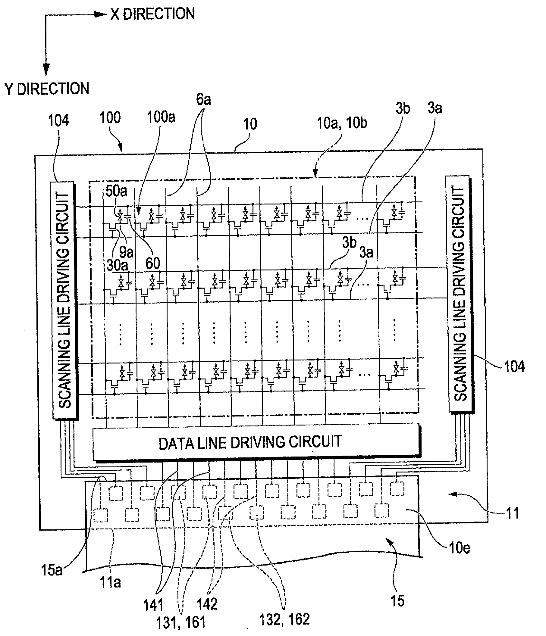
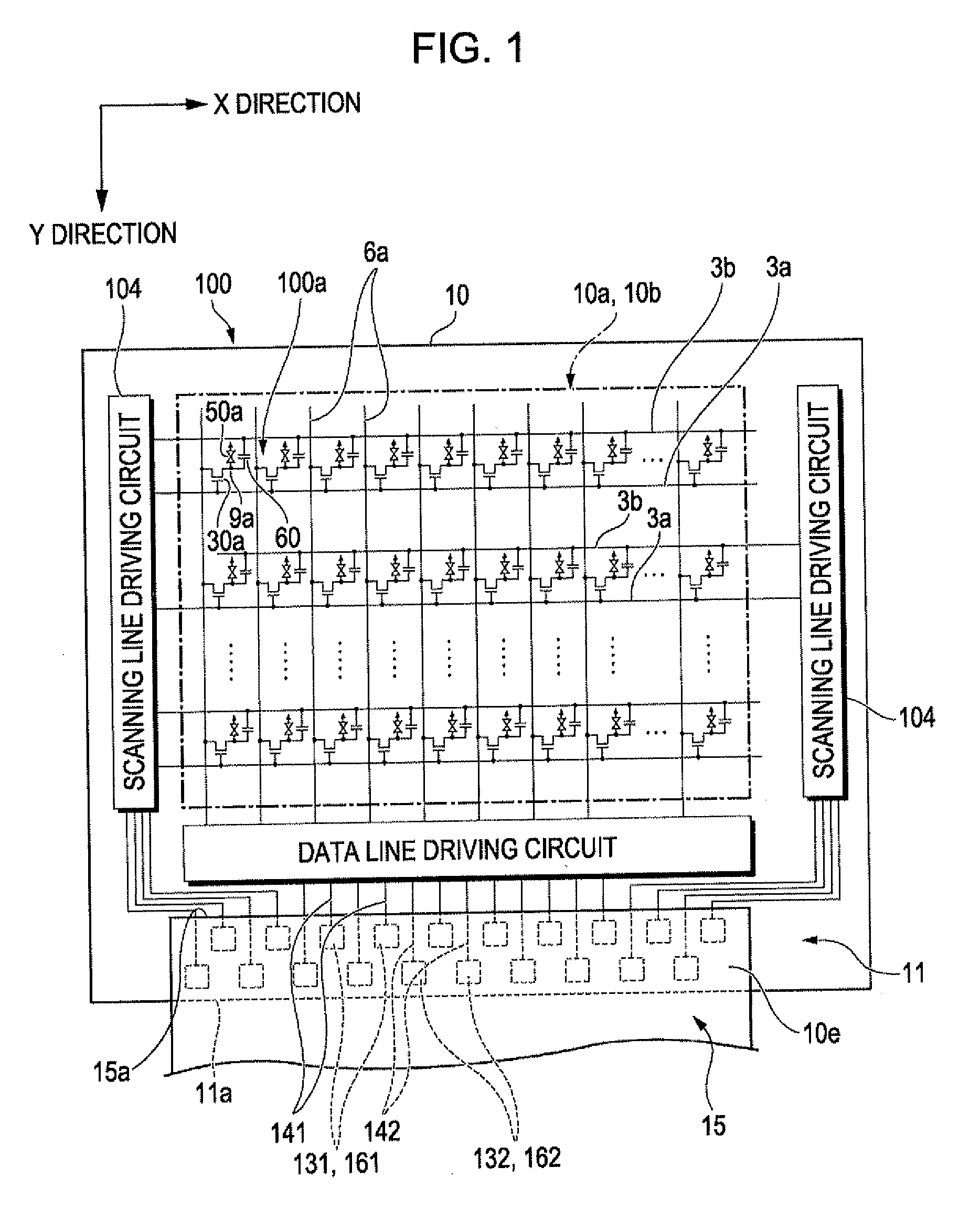
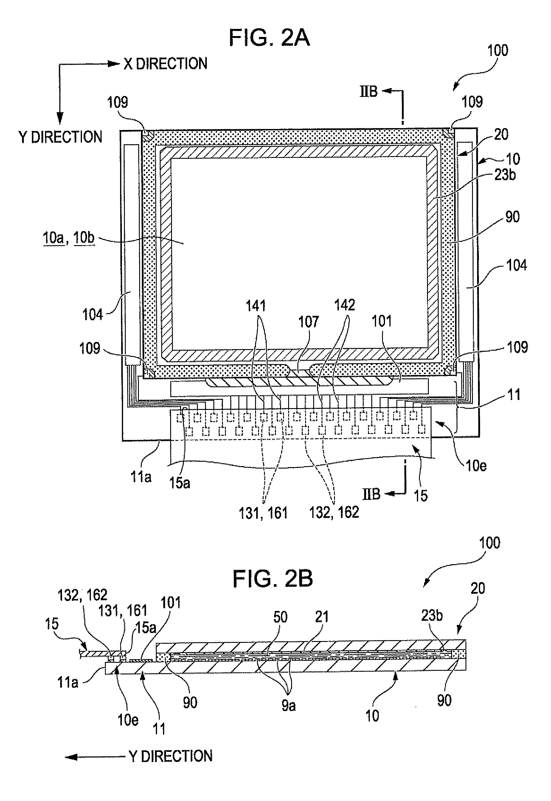
[0051]FIG. 1 is an equivalent circuit diagram showing an electrical structure of a first substrate (element substrate / electro optical device substrate) used in an electro optical device (liquid crystal device) according to a first embodiment of the invention. FIG. 2A is a plan view showing the electro optical device according to the first embodiment of the invention viewed from a side of a counter substrate with each constituent element formed thereon, and FIG. 2B is a cross sectional view thereof taken along the line IIB-IIB of FIG. 2A.
[0052]As shown in FIG. 1, an electro optical device 100 according to the embodiment is a liquid crystal device, and a plurality of pixels 100a are formed in a pixel area 10b in a matrix manner. A pixel electrode Da and a thin film transistor 30a (pixel transistor) for pixel switching for controlling the pixel electrode 9a are formed in each of the plurality of the pixel electrodes 100a. Further, a data line driving circuit 101 and scan...
embodiment
Main Effect of Embodiment
[0075]FIG. 5 is an explanatory diagram schematically showing a planer structure when the positional relationship between the first substrate 10 and the flexible printed circuit 15 is deviated in the Second direction in the mounting are 10e shown in FIG. 3B.
[0076]As described above, in the electro optical device 100 of the embodiment, the first substrate 10 and the flexible printed circuit 15 constitute a mounting structure. In the mounting structure, the plurality of substrate-side first terminals 131 and the plurality of substrate-side second terminals 132 that are aligned in the Second direction are arranged in two rows in the First direction. Further, the substrate-side first terminals 131 and the substrate-side second terminals 132 are formed at positions deviated in the Second direction. Also in the flexible printed circuit 15, the plurality of component-side first terminals 161 and the component-side second terminals 162 are arranged in two rows in the...
second embodiment
[0088]FIG. 6A is a plan view showing an electro optical device (liquid crystal device) according to a second embodiment of the invention viewed from a side of a counter substrate with each constituent element formed thereon, and FIG. 6B is a cross sectional view thereof taken along the line VIB-VIB of FIG. 6A. FIG. 7A is an explanatory diagram schematically showing a planer structure of wirings and terminals formed in a projected area of the first substrate 10 and a driving IC, and FIG. 7B is an explanatory diagram schematically showing a planer structure of an appearance when the driving IC is overlapped with the projected area of the first substrate 10 and the terminals thereof are electrically connected to each other, in the electro optical device according to the second embodiment of the invention. An end among the mounting area of the driving IC at the pixel area side is magnified in FIGS. 7A, 7B. FIG. 8A is an explanatory diagram schematically showing a cross sectional structu...
PUM
| Property | Measurement | Unit |
|---|---|---|
| area | aaaaa | aaaaa |
| widths Wa1 | aaaaa | aaaaa |
| width Wa1 | aaaaa | aaaaa |
Abstract
Description
Claims
Application Information
 - R&D
- Intellectual Property
- Life Sciences
- Materials
- Tech Scout
- Unparalleled Data Quality
- Higher Quality Content
- 60% Fewer Hallucinations
Browse by: Latest US Patents, China's latest patents, Technical Efficacy Thesaurus, Application Domain, Technology Topic, Popular Technical Reports.
© 2025 PatSnap. All rights reserved.Legal|Privacy policy|Modern Slavery Act Transparency Statement|Sitemap|About US| Contact US: help@patsnap.com


