Gate driver circuit and display panel comprising same

A gate drive circuit and display panel technology, applied in static indicators, instruments, etc., can solve the problems of wasteful power consumption, large power consumption, etc., and achieve the effect of reducing wasteful power consumption

Inactive Publication Date: 2017-08-18
AU OPTRONICS CORP
View PDF0 Cites 2 Cited by
  • Summary
  • Abstract
  • Description
  • Claims
  • Application Information

AI Technical Summary

Problems solved by technology

[0005] In the above two gate drive circuits, since the clock signal CK is connected to each shift register, each phase transition of the clock signal CK will charge and discharge its corresponding parasitic capacitance (Loading), resulting in a successful waste of consumption
And because the clock signal CK is the most frequently used control signal in the operation of the shift register circuit, the waste of power consumption generated by it is also very large

Method used


Image

  • Gate driver circuit and display panel comprising same
  • Gate driver circuit and display panel comprising same
  • Gate driver circuit and display panel comprising same

Examples


Embodiment Construction

[0033] The technical solution of the present invention will be described in detail below in conjunction with the accompanying drawings and specific embodiments to further understand the purpose, solution and effect of the present invention, but it is not intended to limit the scope of protection of the appended claims of the present invention.

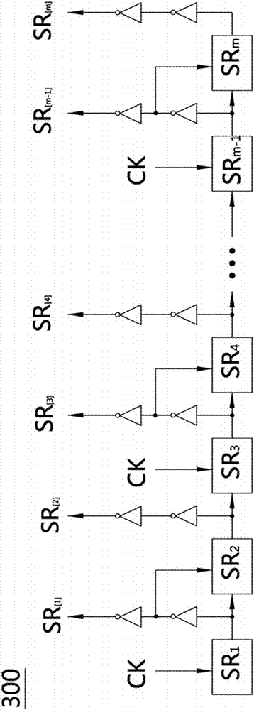
[0034] image 3 It is a partial schematic diagram of the gate driving circuit of the present invention. Please refer to image 3 , the gate drive circuit 300 is used to drive the scan lines of the display panel, and the gate drive circuit 300 includes a multi-stage shift register circuit SR 1 to SR m , multi-stage shift register circuit SR 1 to SR m Used to output multi-level shift signal SR respectively [1] to SR [m] , multi-stage shift register circuit SR 1 to SR m connected in sequence, the output end of the previous stage shift register circuit is connected to the input end of the subsequent stage shift register circuit, an...


PUM


Abstract

The present invention provides a gate drive circuit and a display panel containing it. The gate drive circuit is used for driving the scan lines of the display panel. The gate drive circuit includes a multi-stage shift register circuit, and the multi-stage shift register The circuit is used to output multi-stage shift signals respectively, the multi-stage shift register circuits are connected in sequence, the output end of the previous stage shift register circuit is connected to the input end of the subsequent stage shift register circuit, and each stage shift register circuit passes through The output end outputs a shift signal; wherein, the input end of the odd-numbered shift register circuit in the multi-stage shift register circuit receives a clock signal, and the input of the even-numbered shift register circuit in the multi-stage shift register circuit The terminal is connected to the inversion signal of the shift signal output by the previous stage shift register circuit. The gate drive circuit of the present invention can reduce the waste of power consumption caused by the clock signal continuously charging and discharging the parasitic capacitance during circuit operation.

Description

technical field [0001] The present invention relates to a grid driving circuit and a display panel including it, in particular to a low power consumption grid driving circuit and a display panel including it. Background technique [0002] In a liquid crystal display device, in order to be able to display a picture, a gate driver circuit (gate driver) for driving the scanning line and a source gate driver circuit (Source Driver) for driving the data line are usually provided, wherein the gate driver The circuit is mainly composed of a shift register circuit. At present, the gate driving circuit mainly has the following two ways to drive. [0003] figure 1 It is a partial schematic diagram of a gate driving circuit of a display panel in the prior art. Please refer to figure 1 , the gate drive circuit 100 consists of a shift register SR 1 to SR n The shift registers of odd stages input the clock signal CK, and the shift registers of even stages input the inverted clock si...

Claims


Application Information

Patent Timeline
Patent Type & Authority Applications(China)
IPC IPC(8): G09G3/36
CPCG09G3/3677
Inventor 廖伟见庄铭宏
Owner AU OPTRONICS CORP
Why Eureka
Try Eureka