Self-positioning alignment device for wireless charging

A wireless charging and positioning device technology, applied in the direction of circuit devices, battery circuit devices, current collectors, etc., can solve the problems that limit the wide application of wireless charging technology, can not charge, lose high charging efficiency, etc., to avoid low charging efficiency, Avoid the effect of external force slipping or deflection

Inactive Publication Date: 2017-08-18
NINGBO LIKETEK INFORMATION TECH
View PDF5 Cites 4 Cited by
  • Summary
  • Abstract
  • Description
  • Claims
  • Application Information

AI Technical Summary

Problems solved by technology

[0002] With the rapid development of electronic information technology in our country, the existing wireless charging technology has entered a period of expansive development, but the current wireless chargers based on electromagnetic induction technology have a very serious defect, that is, the coil of the transmitter needs to be connected with the Only when the coils of the receiver are aligned, the charging efficiency can reach the maximum. If the two coils are not aligned, the charging efficiency will be greatly reduced, and even the charging will not be possible.
In addition, even if it has been aligned at the beginning of charging, there will be an offset between the two coils due to various external forces during the charging process, thus losing the original state of high charging efficiency.
It is precisely because of this alignment problem that it greatly limits the wide application of wireless charging technology.

Method used


Image

  • Self-positioning alignment device for wireless charging
  • Self-positioning alignment device for wireless charging
  • Self-positioning alignment device for wireless charging

Examples


Embodiment Construction

[0024] Embodiments of the present invention are described below through specific examples, and those skilled in the art can easily understand other advantages and effects of the present invention from the content disclosed in this specification. The present invention can also be implemented or applied through other different specific implementation modes, and various modifications or changes can be made to the details in this specification based on different viewpoints and applications without departing from the spirit of the present invention. It should be noted that, in the case of no conflict, the following embodiments and features in the embodiments can be combined with each other.

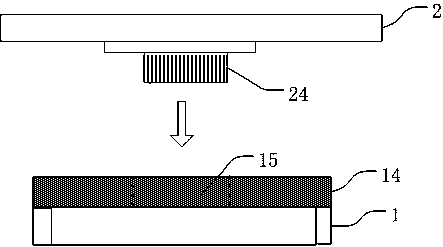
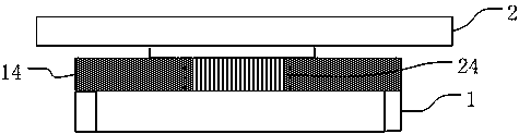
[0025] It should be noted that the diagrams provided in the following embodiments are only schematically illustrating the basic ideas of the present invention, and only the components related to the present invention are shown in the diagrams rather than the number, shape and shape of the compo...


PUM


Abstract

The invention discloses a self-positioning alignment device for wireless charging. The self-positioning alignment device comprises a wireless charging emitter and a wireless charging receiver. The upper surface of the wireless charging emitter is equipped with a first wireless charging positioning device; the center of the first wireless charging positioning device is provided with a run-through circular through hole; the lower surface of the wireless charging receiver is equipped with a second wireless charging positioning device; the second wireless charging positioning device is a raised cylinder structure; and the first wireless charging positioning device and the second wireless charging positioning device are matched and buckled into one body. Through mutual cooperation between the circular through hole and the cylindrical bulge of the first wireless charging positioning device and the second wireless charging positioning device, alignment of wireless charging is realized, thereby avoiding the problem of over-low charging efficiency due to coil deviation caused by external force factors in the charging process.

Description

technical field [0001] The present invention relates to the technical field of wireless charging, in particular to a self-positioning and aligning device for wireless charging. Background technique [0002] With the rapid development of my country's electronic information technology, the existing wireless charging technology has entered a period of expansive development, but the current wireless chargers based on electromagnetic induction technology have a very serious defect, that is, the coil of the transmitter needs to be connected with the The charging efficiency can be maximized only when the coils of the receiver are aligned. If the two coils are not aligned, the charging efficiency will be greatly reduced, and even the charging will not be possible. In addition, even if it has been aligned at the beginning of charging, there will be an offset between the two coils due to various external force factors during the charging process, thus losing the original state of high ...

Claims


Application Information

Patent Timeline
Patent Type & Authority Applications(China)
IPC IPC(8): H02J50/90H02J50/10H02J7/00
CPCH02J5/005H02J7/025
Inventor 林谷
Owner NINGBO LIKETEK INFORMATION TECH
Why Eureka
Try Eureka