
LED drive circuit and control method thereof

A technology of LED driving and control method, which is applied in control/adjustment systems, electric light sources, electrical components, etc., to achieve the effect of suppressing dimming jitter

Active Publication Date: 2017-08-18
HANGZHOU SILAN MICROELECTRONICS
View PDF9 Cites 17 Cited by
  • Summary
  • Abstract
  • Description
  • Claims
  • Application Information

AI Technical Summary

Problems solved by technology

Make the brightness change of LED lights smoother during the dimming process

Method used


Image

  • LED drive circuit and control method thereof
  • LED drive circuit and control method thereof
  • LED drive circuit and control method thereof

Examples


Embodiment Construction

[0052] Hereinafter, the present invention will be described in more detail with reference to the accompanying drawings. In the various figures, identical elements are indicated with similar reference numerals. For the sake of clarity, various parts in the drawings have not been drawn to scale. Also, some well-known parts may not be shown.

[0053] In the following, many specific details of the present invention are described, such as device structures, materials, dimensions, processing techniques and techniques, for a clearer understanding of the present invention. However, the invention may be practiced without these specific details, as will be understood by those skilled in the art.

[0054] The invention can be embodied in various forms, some examples of which are described below.

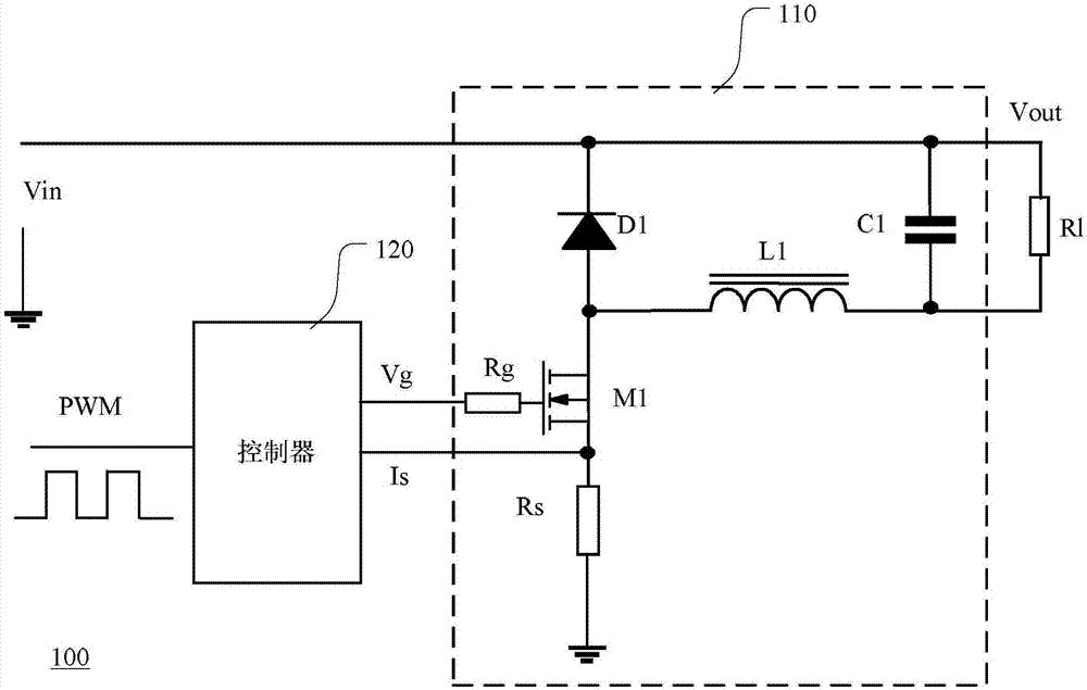
[0055] figure 1 A circuit block diagram of an existing LED driving circuit is shown. The LED driving circuit is a BUCK topology, which is used to step-down transform the DC input voltage V...


PUM


Abstract

The invention discloses an LED drive circuit and a control method thereof. The LED drive circuit includes a main circuit and a control circuit, wherein the main circuit utilizes conduction and disconnection of a switch tube to realize conversion of direct current input voltage to direct current output current; the control circuit provides a driving signal to the switch tube to control conduction state of the switch tube; the control circuit acquires a current detection signal from the main circuit, and executes peak value current control according to the current detection signal and a peak value current reference signal so as to enable the switch tube to switch the conduction state in each switching period of the driving signal; the driving signal has a first duty ratio; the control circuit receives a light modulation signal, and controls output of the driving signal according to the light modulation signal; the light modulation signal has a second duty ratio; and the control circuit includes a peak value current compensation module, and compensates the peak value current reference signal according to the second duty ratio of the light modulation signal so as to restrain light modulation jitter.

Description

technical field [0001] The invention relates to switching power supply technology, more specifically, to a light-emitting diode (LED) dimming device and a driving circuit. Background technique [0002] When LEDs are used in the lighting field, the LED driving circuit is used to adjust the brightness to meet the individual needs of users or adjust the light according to the environment to reduce energy consumption. The LED driving circuit is, for example, a conventional thyristor dimmer or a pulse width modulation (ie, PWM) dimming device. The working principle of the thyristor dimmer is to adjust the output voltage and output current by changing the conduction angle of the AC input voltage. The working principle of the PWM dimming device is to adjust the current flowing through the LED by changing the duty cycle of the PWM signal. Compared with thyristor dimming, the PWM dimming device has low conduction loss, low noise and stable operation, and can reduce electromagnetic ...

Claims


Application Information

Patent Timeline
Patent Type & Authority Applications(China)
IPC IPC(8): H02M3/156H05B33/08H05B44/00
CPCH02M3/156H05B45/10H05B45/37
Inventor 高文亚姚丰林继认蔡拥军
Owner HANGZHOU SILAN MICROELECTRONICS
Learn More