
Method and device to build-up, clad, or hard-face with minimal admixture

Active Publication Date: 2008-01-10
LINCOLN GLOBAL INC
View PDF37 Cites 83 Cited by
  • Summary
  • Abstract
  • Description
  • Claims
  • Application Information

AI Technical Summary

Benefits of technology

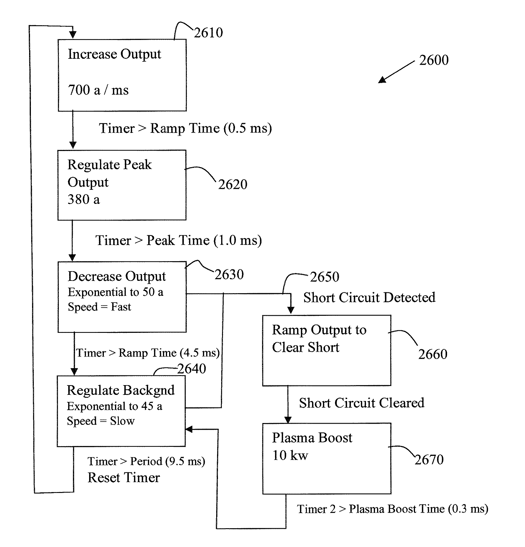
[0006] A first embodiment of the present invention comprises a method of cladding or hard-facing an alloyed metal onto a parent metal with minimal admixture by generating a series of electric arc pulses between an advancing electrode comprising the alloyed metal and a workpiece comprising the parent metal. The method includes increasing an output current level over a first time segment while maintaining an arc between the advancing electrode and the workpiece and regulating the output current level to a peak current level over a second time segment while maintaining the arc between the advancing electrode and the workpiece. The method also includes decreasing the output current level from the peak current level toward a background current level in an attempt to induce a first short of molten metal between the advancing electrode and the workpiece and regulating the output current level to the background current level. The method further includes determining if the first short occurs and ramping the output current level above the background current level, if the short has been determined to occur, until the short is cleared. The method also includes pulsing the output current level over a third time segment to prevent a second short from occurring directly after clearing the first short. The method steps may be repeated at a pre-defined pulse repetition rate for the series of pulses.

Problems solved by technology

In other cases, the cladding or hardfacing weld metal, when applied directly to a base metal, may form an undesirable layer that may not survive in service.
The copper / iron mixture layer (sometimes called admixture) is kept low enough to prevent cracking but this process is limited to the short arc transfer range and is, therefore, slow.
When the procedure is increased to improve productivity, and a traditional GMAW-pulsed spray or GMAW-Spray transfer is used, the heat increases and the mixture of copper and iron increases to an undesirable level.

Method used


Image

  • Method and device to build-up, clad, or hard-face with minimal admixture
  • Method and device to build-up, clad, or hard-face with minimal admixture
  • Method and device to build-up, clad, or hard-face with minimal admixture

Examples


Embodiment Construction

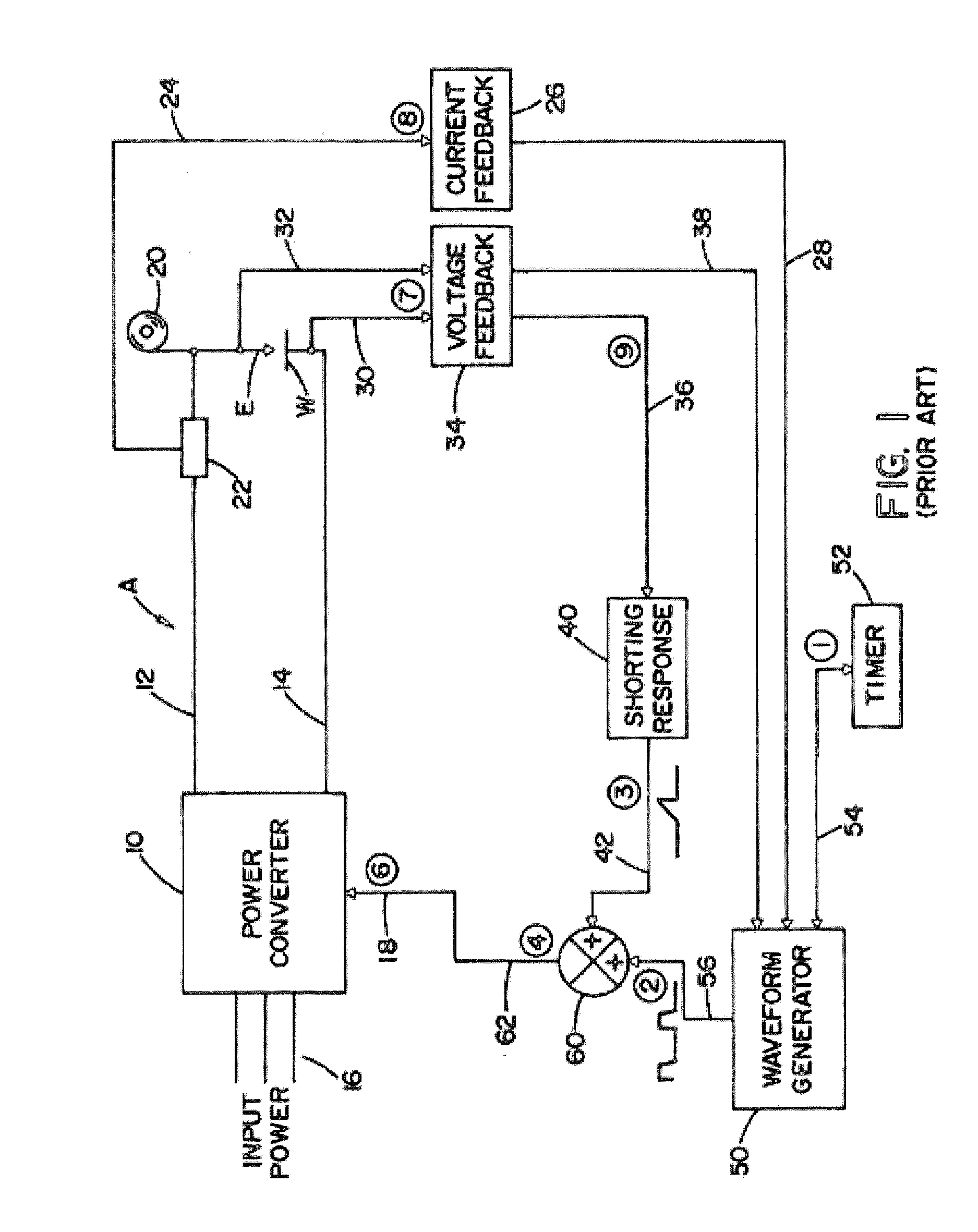
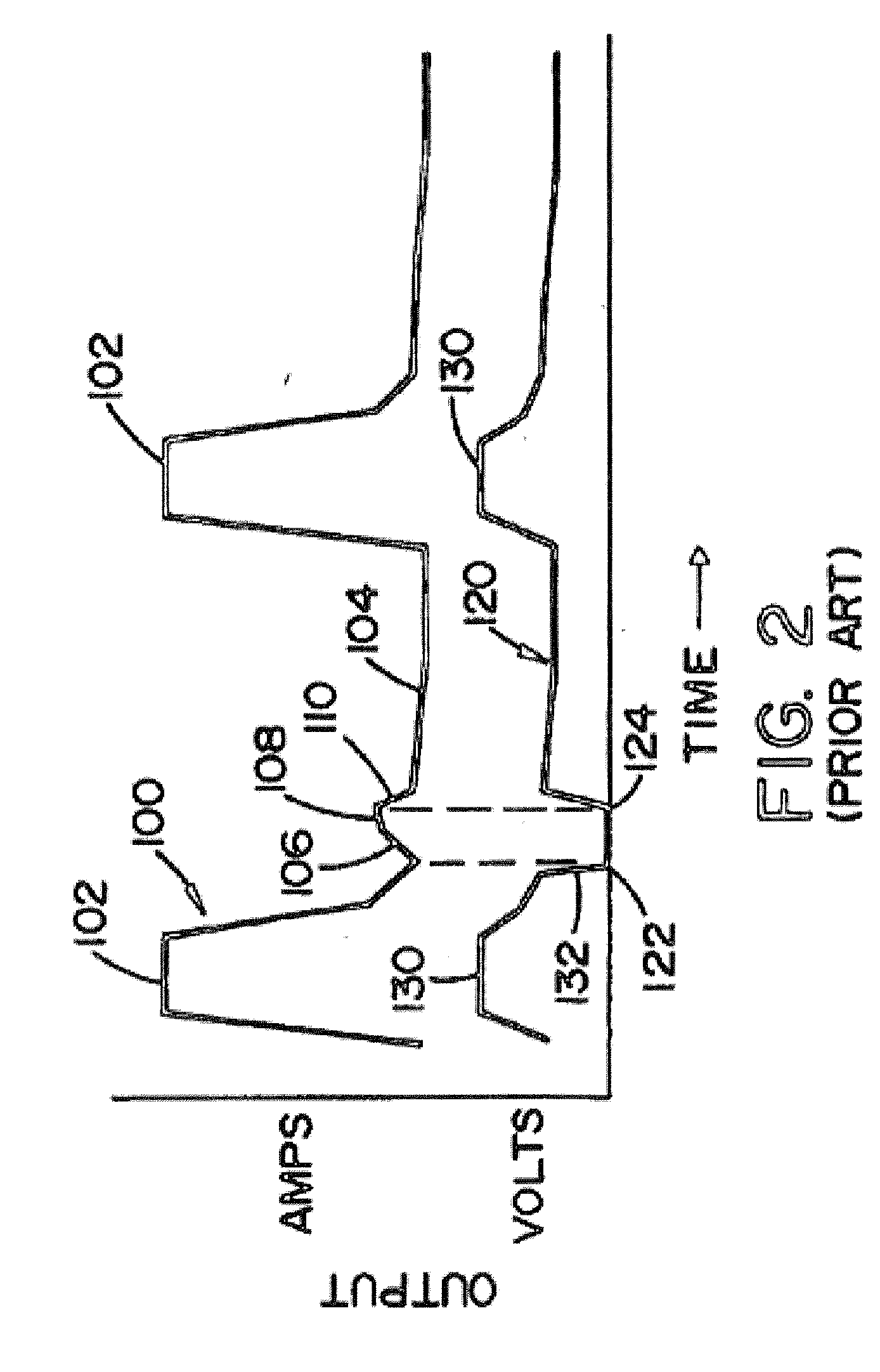
[0037] Referring now to the drawings, wherein the showings are for the purpose of illustrating embodiments of the present invention only and not for the purpose of limiting same, FIGS. 1-3 illustrate a prior art electric arc welder A for performing a pulse welding process, as shown in FIG. 2. The prior art is illustrated since some of the components used in practicing embodiments of the present invention are essentially the same as standard components in electric arc welders. Although other welder architecture could be used, one architecture is a welder controlled by waveform technology as pioneered by The Lincoln Electric Company of Cleveland, Ohio. Two of many patents relating to waveform technology is described in Blankenship U.S. Pat. No. 5,278,390 and Fulmer U.S. Pat. No. 6,498,321, incorporated by reference herein as background information. In this type of welder, a waveform generator produces the profile for the waveforms used in a pulse welding process. The power source crea...


PUM

PropertyMeasurementUnit
Fractionaaaaaaaaaa
Timeaaaaaaaaaa
Timeaaaaaaaaaa

Abstract

An electric arc device and methods to build up, clad, join, or overlay an alloyed metal onto a parent metal with minimal admixture. The methods employed in the electric arc device provide a high frequency waveform with a high amplitude pulse, a low amplitude background current, and a special shorting routine, to alleviate the problem of generating too much ad-mixture. A fast transition from a peak current level to a background current level along with a shorting response and a plasma boost pulse reduces the droplet size and reduces the heat input required to achieve good welding performance.

Description

CROSS-REFERENCE TO RELATED APPLICATIONS / INCORPORATION BY REFERENCE [0001] This U.S. patent application is a continuation-in-part (CIP) of pending U.S. patent application Ser. No. 10 / 861,958, filed on Jun. 4, 2004, which is incorporated herein by reference in its entirety.TECHNICAL FIELD [0002] Certain embodiments relate to an electric arc device and methods of using an electric arc device. More particularly, certain embodiments relate to an electric arc device implementing methods to build-up, clad, or hard-face an alloyed metal onto a parent metal with minimal admixture. BACKGROUND [0003] Arc welding is quite often used as a method to build up, clad, or hardface metal objects, thereby placing a weld metal of a desired alloy onto the surface of another metal. Commonly, the composition of the clad or hardfacing material is significantly more expensive than the metal it is being placed on and therefore it is desirable to minimize the thickness of the weld metal. But in the process of ...

Claims


Application Information

Patent Timeline
IPC IPC(8): B23K9/04B23K9/073B23K9/09
CPCB23K9/04B23K9/0738B23K2203/04B23K9/092B23K9/09B23K2103/04B23K2103/05
Inventor PETERS, STEVEN R.MORLOCK, MICHAEL J.FULMER, BRUCE E.HEARN, JAMES E.
Owner LINCOLN GLOBAL INC
Learn More