Laminated-type varistor

a technology of varistor and laminated type, which is applied in the direction of resistor details, current responsive resistors, varistors, etc., can solve the problems of varistor easily broken, surge-absorbing action is not sufficient, and the maximum peak current of the laminated type varistor described above is not sufficien

Inactive Publication Date: 2000-11-14
MURATA MFG CO LTD
View PDF5 Cites 83 Cited by
  • Summary
  • Abstract
  • Description
  • Claims
  • Application Information

AI Technical Summary

Problems solved by technology

However, the laminated-type varistor described above does not have a sufficient maximum peak current or a sufficient maximum energy, and has a high contact resistance between the internal and external electrodes (connection resistance).
Accordingly, such a varistor is easily broken due to heat generated by surge absorption.
Further, since the contact resistance (connection resistance) between the internal electrodes and the external electrodes is high and therefore the clamping voltage at the time of surge absorption is high, the surge-absorbing action is not su

Method used


Image

  • Laminated-type varistor
  • Laminated-type varistor
  • Laminated-type varistor

Examples


embodiment 1

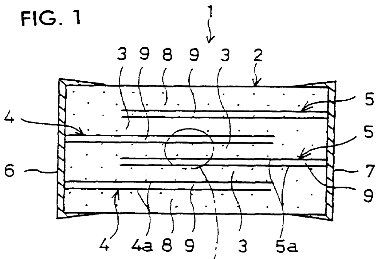
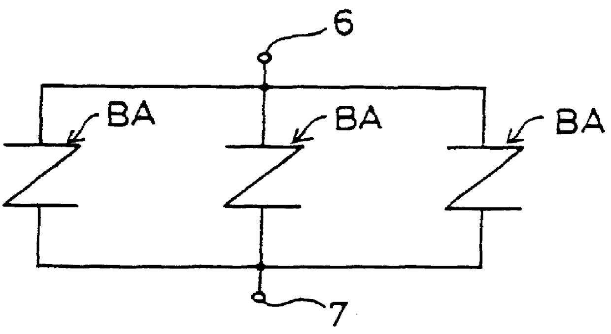
FIG. 1 is a section view of a laminated-type varistor according to the present embodiment. FIG. 2 is an equivalent circuit view of the laminated-type varistor according to the present embodiment.

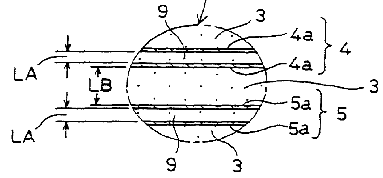
As shown in FIG. 1, the laminated-type varistor 1 is a chip-type varistor comprising a laminated structure 2 and a pair of external electrodes 6 and 7 disposed on a surface of the laminated structure 2. The laminated structure 2 consists of effective sintered body layers 3, each of which exhibits the varistor characteristics, and four internal electrodes 4 and 5, which have a larger heat conductivity than the effective sintered body layer 3.

The two internal electrodes 4 of the laminated-type varistor 1 are connected to an external electrode 6, and the other two internal electrodes 5 are connected to the other external electrode 7. The voltage applied between the external electrodes 6 and 7 is then applied to each of the effective sintered body layers 3 via the internal electrodes 4 and 5. Pr...

embodiment 2

Next will be described a laminated-type varistor according to another embodiment of the present invention. FIG. 5 is a sectional view showing a laminated-type varistor of Embodiment 2. FIG. 6 is an equivalent circuit diagram of the laminated-type varistor of Embodiment 2.

A laminated-type varistor 10 (FIG. 5) has a structure and effects similar to those of Embodiment 1 except for a two-stage varistor structure. In order to avoid redundant description, only different features will be described, while the description of similar features is omitted.

In the laminated-type varistor 10, an internal electrode 12 connected to one external electrode 6 and an internal electrode 13 connected to the other external electrode 7 are disposed on the same plane such that unconnected ends thereof face each other a predetermined distance away. A floating internal electrode 14 is disposed apart from the internal electrodes 12 and 13 via the effective sintered body layer 3. Thus, as shown in FIG. 6, a two...

embodiment 3

Next will be described a laminated-type varistor according to a further embodiment of the present invention. FIG. 9 is a sectional view showing a laminated-type varistor of Embodiment 3.

A laminated-type varistor 15 of Embodiment 3 has a structure and effects similar to those of Embodiment 1 except that the varistor structure has two more laminae and that the thickness of the ineffective sintered body layer 9 is about 1 / 6 that of the effective sintered body layer 3. In order to avoid redundant description, the description of the structure and effects will be omitted.

A method for manufacturing the laminated-type varistor 15 of Embodiment 3 will be described specifically.

98.6 mol % of ZnO material having a purity of not less than 99%, 0.3 mol % of Bi.sub.2 O.sub.3, 0.5 mol % of CoCO.sub.3, 0.5 mol % of MnO.sub.2, and 0.1 mol % of Sb.sub.2 O.sub.3 were prepared by weighing, followed by addition of pure water and balls. The resulting mixture was mixed and pulverized for 24 hours through ...


PUM


Abstract

A laminated-type varistor includes a laminated structure and a pair of external electrodes disposed on a surface of the laminated structure. The laminated structure includes effective sintered body layers and internal electrodes. The internal electrodes are connected to the external electrodes and are disposed apart from each other in the direction perpendicular to lamination surfaces. Each of the internal electrodes has a multilayer electrode structure in which a plurality of electrode layers are arranged in layers while an ineffective sintered body layer is disposed therebetween. The laminated-type varistor has increased maximum peak current and maximum energy and reduction in clamping voltage.

Description

1. Field of the InventionThe present invention relates to a laminated-type varistor, and particularly to a laminated-type varistor having an increased maximum peak current, an increased maximum energy, and a reduced clamping voltage.2. Related ArtAs shown in FIG. 17A, a laminated-type varistor 40, which is of a chip type and can be surface-mounted, usually comprises a laminated structure 41 and a pair of external electrodes 44a and 44b disposed on a surface of the laminated structure 41. The laminated structure 41 consists of effective sintered body layers 42, each of which provides varistor characteristics, and a plurality of internal electrodes 43a and 43b, which have a higher heat conductivity than do the effective sintered body layers 42 (see Japanese Patent Application Laid-Open (kokai) No. 54-106894.)The laminated-type varistor 40 has been widely used, for example, as a surge-absorbing element, because of its nonlinear resistance characteristics (the varistor characteristics);...

Claims


Application Information

Patent Timeline
IPC IPC(8): H01C7/18H01C7/10
CPCH01C7/18H01C7/10
Inventor HADANO, KENJIROKAWADA, TSUYOSHIFUKUTANI, IWAONAKAMURA, KAZUTAKAKANEKO, KUZUHIROURAHARA, RYOUICHI
Owner MURATA MFG CO LTD
Why Eureka
Try Eureka