
Continuous phase multi-carrier modulation method

A multi-carrier modulation and phase modulation technology, which is applied in the modulation carrier system, multi-frequency code system, digital transmission system, etc., can solve the problem of high bit error rate in multi-carrier transmission and reception, and achieve the effect of reducing bit error rate and improving performance

Inactive Publication Date: 2017-08-18
GUILIN UNIV OF ELECTRONIC TECH
View PDF3 Cites 1 Cited by
  • Summary
  • Abstract
  • Description
  • Claims
  • Application Information

AI Technical Summary

Problems solved by technology

[0003] Aiming at the deficiencies of the above-mentioned prior art, the technical problem to be solved by the present invention is how to solve the problem of high bit error rate of multi-carrier transmission reception in complex wireless transmission environment

Method used


Image

  • Continuous phase multi-carrier modulation method
  • Continuous phase multi-carrier modulation method
  • Continuous phase multi-carrier modulation method

Examples


Embodiment 1

[0046] In this example, the filtered multi-tone modulation is used as the comparison object, wherein the filtered multi-tone modulation is multi-carrier modulation, and has better anti-frequency deviation performance than OFDM multi-carrier.

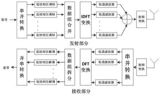
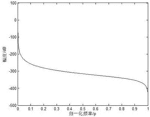
[0047] according to figure 1 Establish a continuous phase multi-carrier modulation model. First send N*L symbols, where N=128, L=64, in this embodiment, after serial-to-parallel conversion, 128 continuous phase maps will be generated, and the length of the filter of the prototype is D=16*K=16* M, where the power spectrum of the prototype filter is as image 3 As shown, the time-domain impulse response of the prototype filter is shown as Figure 4 shown. In the embodiment, the method model provided by the present invention carries out 300 iterations, and the comparison results are as follows: Figure 5 shown. Depend on Figure 5 When the modulation order of continuous phase modulation is octal, it is at BER-6 , the bit error rate is...

Embodiment 2

[0049] This embodiment compares the influence of the difference of the modulation index h of the continuous phase on the bit error rate of the communication transmission system when the continuous phase modulation order is quaternary. according to figure 1 A continuous phase multi-carrier modulation model is established. First send N*L symbols, where N=128, L=64, in this embodiment, after serial-to-parallel conversion, 128 continuous phase maps will be generated, and the length of the filter of the prototype is D=16*K=16* M, the power spectrum of the filter in its prototype is as image 3 As shown, the time-domain impulse response of the prototype filter is shown as Figure 4 shown. In the embodiment, the method model provided by the present invention carries out 300 iterations, and the comparison results are as follows: Figure 6 shown. Depend on Figure 6 When the modulation order of continuous phase modulation is quaternary, when the modulation index h=1.2 and h=2 / 5, ...


PUM


Abstract

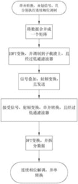
The invention discloses a continuous phase multi-carrier modulation method. A transmitting part carries out serial-to-parallel conversion on a baseband signal, thereby dividing the baseband signal into multiway signals, carries out continuous phase modulation of the same modulation parameter on the divided signals, carries out data array combination on modulated data, carries out IDFT on data arrays, processes the transformed data through lowpass filters, combines all signals, carries out radio frequency transform on the signals and transmits the signals through an antenna. A receiving part carries out radio frequency and serial-to-parallel conversion on the signals received by the antenna, processes the signals through the corresponding lowpass filters, carries out DFT on the processed signals, carries out data array split on the transformed signals and carries out continuous phase demodulation on the split data. According to the method, through utilization of the feature that the spectral efficiency of the continuous phase modulation is high, a bit error rate in a wireless transmission complex environment is reduced, and the transmission capability of a communication system is improved.

Description

technical field [0001] The invention relates to multi-carrier modulation technology, in particular to a continuous phase multi-carrier modulation method. Background technique [0002] The multi-carrier modulation technology divides the channel into multiple sub-channels to transmit data in parallel. This parallel transmission mechanism widens the symbol interval of the signal on each sub-carrier, which can effectively weaken the multipath fading caused by the wireless channel. However, in the mobile environment, the wireless transmission environment is complex, which brings difficulties and challenges to the reception of communication transmission, which causes distortion of the received signal and a high transmission bit error rate. The fading characteristics of the wireless channel affect the multi-carrier modulation transmission technology, and the modulation method of the signal will make a great difference in the performance of the communication system, so an appropriat...

Claims


Application Information

Patent Timeline
Patent Type & Authority Applications(China)
IPC IPC(8): H04L27/26H04L1/00
CPCH04L27/2628H04L1/0054H04L27/265
Inventor 谢跃雷甘梓兴杨子靖李永强李文山刘威农茜雯欧阳缮丁勇蒋俊正
Owner GUILIN UNIV OF ELECTRONIC TECH
Learn More