Valve device for a motor vehicle

A valve device, motor vehicle technology, applied in valve devices, machines/engines, lift valves, etc., can solve problems such as increased cost and complex shell design, and achieve the effects of reducing the risk of damage, high adjustment quality, and increased sealing effect

Inactive Publication Date: 2017-08-18
CONTINENTAL AUTOMOTIVE GMBH
View PDF6 Cites 1 Cited by
  • Summary
  • Abstract
  • Description
  • Claims
  • Application Information

AI Technical Summary

Problems solved by technology

The disadvantage of this valve arrangement is the complex housing design due to the coolant channels and the connections to them
Designing the flow channels with anti-icing coatings is also disclosed, but this leads to increased costs

Method used


Image

  • Valve device for a motor vehicle
  • Valve device for a motor vehicle
  • Valve device for a motor vehicle

Examples


Embodiment approach

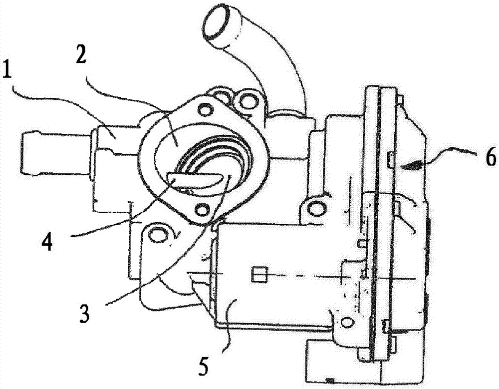
[0024] figure 1 The figure shows a throttle nozzle as a valve arrangement, with a housing 1 , a flow channel 2 in the housing, in which a disk-shaped flap 3 is arranged. The valve flap 3 is fixedly connected to a shaft 4 and the shaft 4 is rotatably mounted in the housing 1 . The electric motor 5 drives the shaft 4 via a transmission 6 .

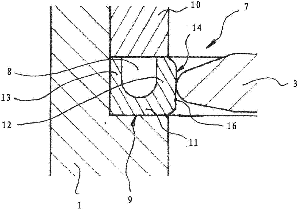
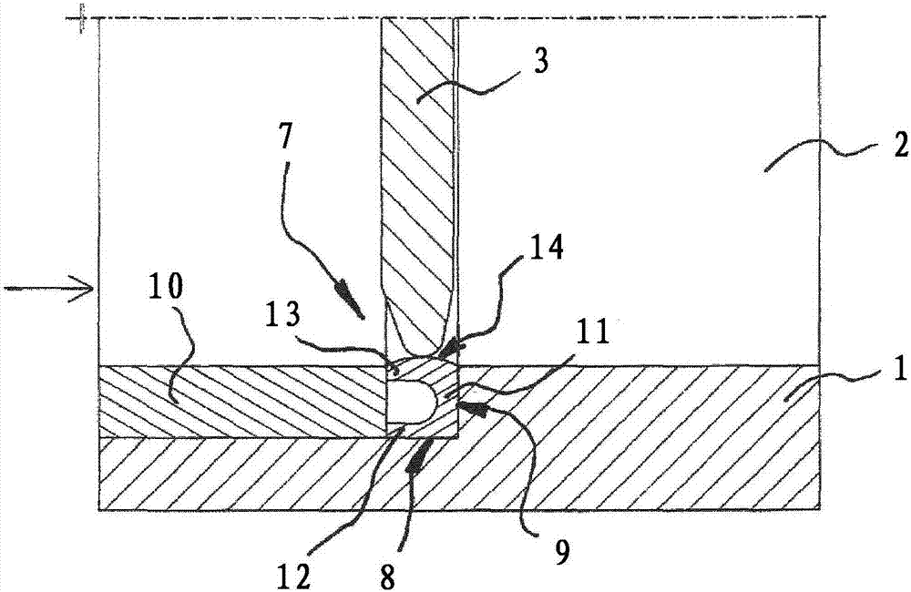
[0025] The cylindrical region in which the valve flap 3 seals the flow channel 2 is the valve seat 7 . The direction of flow in flow channel 2 is indicated by arrows. figure 2 The flap 3 is shown in the closed position in the flow channel 2 . For this purpose, the valve flap 3 bears against the seal 8 . The seal 8 rests against a shoulder of the flow channel 2 designed as a receptacle 9 and is held in this position by a locking ring 10 . The seal 8 has a U-shaped cross-section, wherein the corner top 11 and the leg 12 of the seal 8 rest on the shoulder 9 , and the leg 13 is in contact with the valve flap 3 . The leg 13 facing the flap...


PUM


Abstract

The invention relates to a valve device for a motor vehicle, comprising a housing (1), a flow channel (2) located in the housing, a flap (3) arranged in the flow channel (2) for closing the flow channel (2), said flap (3) having regions in which a pin (4) penetrating the flap (3) is fastened and said pin (4) is rotatably mounted in the housing (1), and a valve seat (7), which is arranged in the flow channel (2) and which is in contact with the flap (3) when the latter is in the closed position. The seal (8) is arranged in the flow channel, the side of the seal (8) facing the flap (3) having a wall thickness (14) which is greater than the rest of the cross-sectional surface, said area (14) being opposite the flap (3) in the closed state.

Description

technical field [0001] The invention relates to a valve arrangement for a motor vehicle with a housing, a flow channel in the housing, a valve plate arranged in the flow channel for closing the flow channel, and a valve arranged in the flow channel A seat, wherein the valve flap is fixed on a shaft, the shaft is rotatably supported in the housing, and the valve seat is in contact with the valve flap when the valve flap is in the closed position. Background technique [0002] Such valve arrangements are used, for example, as throttle nozzles or exhaust gas recirculation valves and are already known. The rotatably mounted valve flap can completely close or open the flow channel in order to adjust the mass flow rate accordingly. Since a high adjustment quality is required especially in the region with small opening angles, the flap design and the sealing design are of particular importance. On the one hand, the seal is subjected to strong mechanical loads due to opening and c...

Claims


Application Information

Patent Timeline
Patent Type & Authority Applications(China)
IPC IPC(8): F16K1/226F02D9/10F02M26/70
CPCF02D9/1045F16K1/2266F02M26/70F02M26/73F02M26/72
Inventor P·科伦R·J·蒙蒂尼
Owner CONTINENTAL AUTOMOTIVE GMBH
Why Eureka
Try Eureka