Directed self-assembly of electronic components using diamagnetic levitation

A diamagnetic, component technology, applied in diamagnetic/paramagnetic materials, electric components, holding devices with magnetic attraction or thrust, etc., can solve problems such as slowness, impossible and impractical use of robots

Active Publication Date: 2017-08-18
RENESSELAER POLYTECHNIC INST
View PDF3 Cites 9 Cited by
  • Summary
  • Abstract
  • Description
  • Claims
  • Application Information

AI Technical Summary

Problems solved by technology

However, in some cases, the use of such robots has become impossible or impractical
For example, the assembly of large numbers of very small (e.g., mesoscopic or microscopic) components on large substrates using pick-and-place robots has proven difficult, slow, and therefore very expensive

Method used


Image

  • Directed self-assembly of electronic components using diamagnetic levitation
  • Directed self-assembly of electronic components using diamagnetic levitation
  • Directed self-assembly of electronic components using diamagnetic levitation

Examples


Embodiment Construction

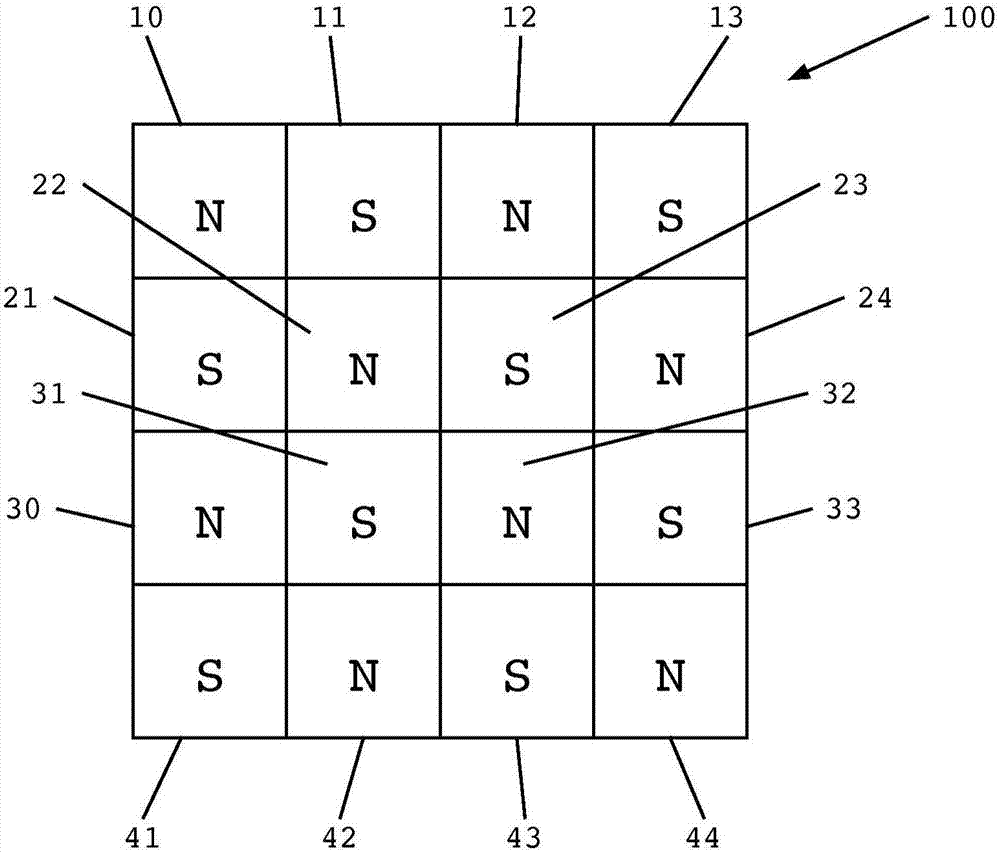
[0023] Referring now to the accompanying drawings, figure 1 A schematic top view of a magnetic table 100 suitable for use in accordance with various embodiments of the invention is shown. The magnetic table 100 includes a plurality of magnets arranged in rows and columns with alternating poles facing upward, similar to a checkerboard pattern. That is, the first row of magnets includes "northup" magnets 10 and 12 alternating with "south up" magnets 11 and 13, while the second row of magnets includes "northup" magnets 22 and 24 alternate "south up" magnets 21 and 23. The third and fourth rows of magnets repeat the pattern such that each pole on the surface of the magnetic table 100 adjoins with opposite polarity above, below, and on each side thereof, and with the same polarity diagonally. adjacent.

[0024] Such as figure 1 As shown, the magnetic table 100 comprises a "four by four" square. However, those skilled in the art will appreciate that the magnetic table 100 may b...


PUM

PropertyMeasurementUnit
thicknessaaaaaaaaaa
thicknessaaaaaaaaaa

Abstract

Embodiments of the invention relate generally to directed self-assembly (DSA) and, more particularly, to the DSA of electronic components using diamagnetic levitation.

Description

[0001] Cross References to Related Applications [0002] This application claims priority to co-pending US Provisional Patent Application No. 62 / 064,629, filed October 16, 2014, which is hereby incorporated as if fully set forth. [0003] Statement Regarding Federally Sponsored Research or Development [0004] This invention was made with government support under Contract No. EEC-0812056 awarded by the National Science Foundation. The government has certain rights in this invention. Background technique [0005] Currently, the assembly of electronic components involves the use of "pick and place" robots that physically lift and move the components into the desired configuration. However, in some cases, the use of such robots has become impossible or impractical. For example, the assembly of large numbers of very small (eg, mesoscopic or microscopic) components on large substrates using pick-and-place robots has proven difficult, slow, and therefore very expensive. This sce...

Claims


Application Information

Patent Timeline
Patent Type & Authority Applications(China)
IPC IPC(8): H02K1/27B23P19/10H01F1/053
CPCH01F1/0018B81C3/005B81C2203/057H01F7/0247H01L2224/95085H01F7/0236H02K1/27B23P19/033B23P19/04B23P19/107H01F1/055H01F1/057H01F1/12H01F7/127H01L21/02104H01L21/67121H01L21/68H01L21/82H02K1/06H02K1/2753H02N15/00H02N15/04
Inventor A·特卡琴科J·J-q·卢
Owner RENESSELAER POLYTECHNIC INST
Why Eureka
Try Eureka