Efficient deburring equipment for brake clutch disc
A technology for removing burrs and clutch plates, which is applied in metal processing equipment, grinding/polishing equipment, grinding machines, etc., and can solve problems such as inconvenient movement, cumbersome operation, and poor deburring effect
- Summary
- Abstract
- Description
- Claims
- Application Information
AI Technical Summary
Problems solved by technology
Method used
Image

Examples
Embodiment 1
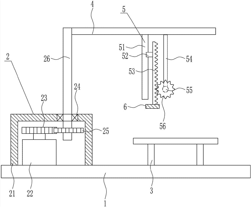
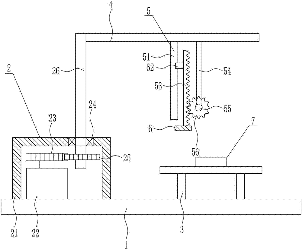
[0037] A kind of high-efficiency deburring equipment for brake clutch plates, such as Figure 1-7 As shown, it includes a bottom plate 1, a rotating device 2, a placing table 3, a top plate 4, a lifting device 5 and a grinding block 6. The top of the bottom plate 1 is provided with a rotating device 2 and a placing table 3, and the rotating device 2 is located on the left side of the placing table 3. The rotating part of the rotating device 2 is connected with a top plate 4, and the top plate 4 is horizontally arranged, and a lifting device 5 is arranged in the middle of the bottom of the top plate 4, and a grinding block 6 is connected on the lifting part of the lifting device 5.
Embodiment 2
[0039] A kind of high-efficiency deburring equipment for brake clutch plates, such as Figure 1-7 As shown, it includes a bottom plate 1, a rotating device 2, a placing table 3, a top plate 4, a lifting device 5 and a grinding block 6. The top of the bottom plate 1 is provided with a rotating device 2 and a placing table 3, and the rotating device 2 is located on the left side of the placing table 3. The rotating part of the rotating device 2 is connected with a top plate 4, and the top plate 4 is horizontally arranged, and a lifting device 5 is arranged in the middle of the bottom of the top plate 4, and a grinding block 6 is connected on the lifting part of the lifting device 5.
[0040] The rotating device 2 includes an N-shaped frame 21, a first motor 22, a first gear 23, a bearing seat 24, a second gear 25 and a rotating rod 26, and the left side of the top of the base plate 1 is equipped with an N-shaped frame 21 by means of bolt connection, The top of the bottom plate 1...
Embodiment 3
[0042] A kind of high-efficiency deburring equipment for brake clutch plates, such as Figure 1-7 As shown, it includes a bottom plate 1, a rotating device 2, a placing table 3, a top plate 4, a lifting device 5 and a grinding block 6. The top of the bottom plate 1 is provided with a rotating device 2 and a placing table 3, and the rotating device 2 is located on the left side of the placing table 3. The rotating part of the rotating device 2 is connected with a top plate 4, and the top plate 4 is horizontally arranged, and a lifting device 5 is arranged in the middle of the bottom of the top plate 4, and a grinding block 6 is connected on the lifting part of the lifting device 5.
[0043] The rotating device 2 includes an N-shaped frame 21, a first motor 22, a first gear 23, a bearing seat 24, a second gear 25 and a rotating rod 26, and the left side of the top of the base plate 1 is equipped with an N-shaped frame 21 by means of bolt connection, The top of the bottom plate 1...
PUM
 Abstract
Description
Claims
Application Information
 - R&D
- Intellectual Property
- Life Sciences
- Materials
- Tech Scout
- Unparalleled Data Quality
- Higher Quality Content
- 60% Fewer Hallucinations
Browse by: Latest US Patents, China's latest patents, Technical Efficacy Thesaurus, Application Domain, Technology Topic, Popular Technical Reports.
© 2025 PatSnap. All rights reserved.Legal|Privacy policy|Modern Slavery Act Transparency Statement|Sitemap|About US| Contact US: help@patsnap.com