
Optical fiber annealing extending pipe

An extension tube and annealing technology, which is applied in manufacturing tools, glass manufacturing equipment, glass production, etc., can solve the problems of reducing the strength of optical fibers, affecting gas flow, and affecting the quality of optical fibers, so as to reduce fiber breakage rate, improve production efficiency, and improve The effect of brushed quality

Active Publication Date: 2017-08-22
JIANGSU HENGTONG OPTICAL FIBER TECH +1
View PDF11 Cites 5 Cited by
  • Summary
  • Abstract
  • Description
  • Claims
  • Application Information

AI Technical Summary

Problems solved by technology

The optical fiber annealing extension tube is set under the drawing furnace to prevent the fiber from being quenched and affecting its performance. Traditional optical fiber annealing mostly uses a combination of graphite liner and metal tube. For example, the optical fiber disclosed in Chinese patents CN201121163Y and CN102079623B The annealing device is simple to operate and has strong practicability. It has a certain effect on the annealing of the optical fiber. However, due to the limitation of the material of the metal itself, under the influence of high and low temperature cycles for a long time, the metal deformation is serious, which affects the quality of the optical fiber.
[0003]On the other hand, as the size of the preform gradually increases, the drawing time of a single light rod gradually increases (currently the longest drawing time can be 6 days left and right), leading to an increase in the oxides produced in the fiber optic furnace. When the wire is drawn to the end of the optical rod, the oxides and volatiles gradually accumulate and increase into the annealing extension tube, and the narrow space in the annealing extension tube is easily blocked by oxides and volatiles It affects the gas flow and causes fluctuations in the bare fiber. At the same time, volatiles are easy to fall again and adhere to the surface of the bare fiber. Even at high temperatures, SiC particles will enter the interior of the bare fiber, resulting in microcracks on the surface of the fiber. Increases the surface defects of the optical fiber, reduces the strength of the optical fiber, and adversely affects the mechanical properties, screening tests, and cabled characteristics of the subsequent optical fiber

Method used


Image

  • Optical fiber annealing extending pipe
  • Optical fiber annealing extending pipe
  • Optical fiber annealing extending pipe

Examples


Embodiment

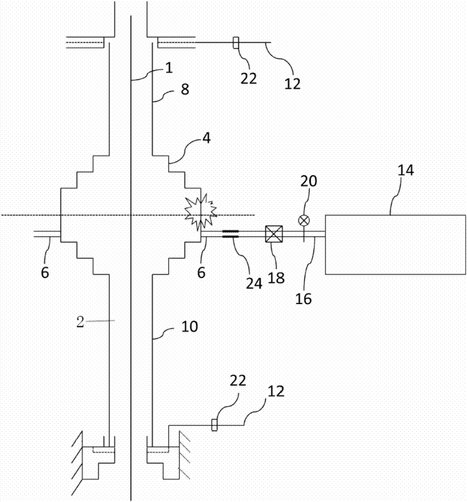
[0029] Such as figure 1 As shown, this embodiment discloses an optical fiber annealing extension tube, which includes a quartz main tube 2, which is connected to the drawing furnace. When in use, the optical fiber 1 passes through the central axis hole in the quartz main tube 2, and the above-mentioned reducing tube section 4 A quartz branch pipe 6 is connected to the top, and the above-mentioned quartz branch pipe 6 is connected to the maximum pipe diameter of the variable diameter pipe section 4. The above-mentioned quartz branch pipe 4 communicates with the quartz main pipe 2, and the other end of the above-mentioned quartz branch pipe 6 is connected with a negative pressure suction device; In the technical solution of the invention, the central part of the above-mentioned quartz main pipe 2 in the axial direction is a variable-diameter pipe section 4, and the pipe diameters of the above-mentioned quartz main pipe 2 located on both sides of the variable-diameter pipe section...


PUM

PropertyMeasurementUnit
lengthaaaaaaaaaa

Abstract

The invention provides an optical fiber annealing extending pipe, which comprises a quartz main pipe, wherein the middle position in the axial direction of the quartz main pipe is a variable-diameter pipe section; the pipe diameters of the pipe body, positioned at the two sides of the variable-diameter pipe section, of the quartz main pipe are smaller than the minimum pipe diameter in the variable-diameter pipe section; a quartz branch pipe is connected onto the variable-diameter pipe section; the quartz branch pipe is connected in the maximum pipe diameter position of the variable-diameter pipe section; the quartz branch pipe communicates with the inside of the quartz main pipe; the other end of the quartz branch pipe is connected with a negative pressure suction device; the pipe diameter of the upward middle pipe section of the variable-diameter pipe section is maximum; the pipe diameters of the pipe body, positioned at the two sides of the middle pipe section, of the variable-diameter pipe section are gradually reduced. The quartz main pipe using the optimized structure design is matched with the negative pressure suction device and can be used for performing online cleaning treatment on oxide, volatile substances and the like entering the annealing extending pipe; on the premise of ensuring the optical fiber quality, the optical fiber fracture rate is reduced; the production efficiency is improved.

Description

technical field [0001] The invention belongs to the technical field of quartz optical fibers, and in particular relates to an optical fiber annealing extension tube. Background technique [0002] With the recovery of the optical fiber market, the demand for optical fiber in the market is increasing day by day, and major optical fiber manufacturers are speeding up and improving production efficiency to meet market demand. The fiber annealing extension tube is set under the drawing furnace to prevent the fiber from being suddenly cooled after being pulled out and affecting its performance. Traditional fiber annealing mostly uses a combination of graphite liner and metal tube, for example, the optical fiber disclosed in Chinese patents CN201121163Y and CN102079623B The annealing device is easy to operate and has strong practicability. It has a certain effect on the annealing of the optical fiber. However, due to the limitation of the material of the metal itself, under the infl...

Claims


Application Information

Patent Timeline
Patent Type & Authority Applications(China)
IPC IPC(8): C03B37/10
CPCC03B37/10Y02P40/57
Inventor 郝昌平宋海瑞陈伟罗干董魏曹少波贺作为张良袁健
Owner JIANGSU HENGTONG OPTICAL FIBER TECH
Learn More