
A powder spraying machine for alloy workpieces

A powder sprayer and metal workpiece technology, applied in the direction of pressure inorganic powder coating, can solve the problems of low work efficiency, rework, scattered powder, etc., to save labor costs, improve work efficiency, and avoid waste.

Active Publication Date: 2019-02-26
ZUNYI ZHONGBO CEMENTED CARBIDE
View PDF8 Cites 0 Cited by
  • Summary
  • Abstract
  • Description
  • Claims
  • Application Information

AI Technical Summary

Problems solved by technology

The existing powder spraying is to place multiple workpieces in a closed space, and the powder sprayed by the spray gun is adsorbed on the workpieces, but this kind of equipment occupies a large area, and for some workpieces with complex structures and shapes, the spraying process is difficult. , there is a problem that the dead corners cannot be sprayed and too much powder is accumulated in some places, the spraying is uneven, the spraying pass rate is low, and rework or re-spraying is required, which wastes production costs and low work efficiency
Moreover, the powder is scattered around during the spraying process, causing serious waste

Method used


Image

  • A powder spraying machine for alloy workpieces

Examples


Embodiment Construction

[0017] The present invention will be described in further detail below by means of specific embodiments:

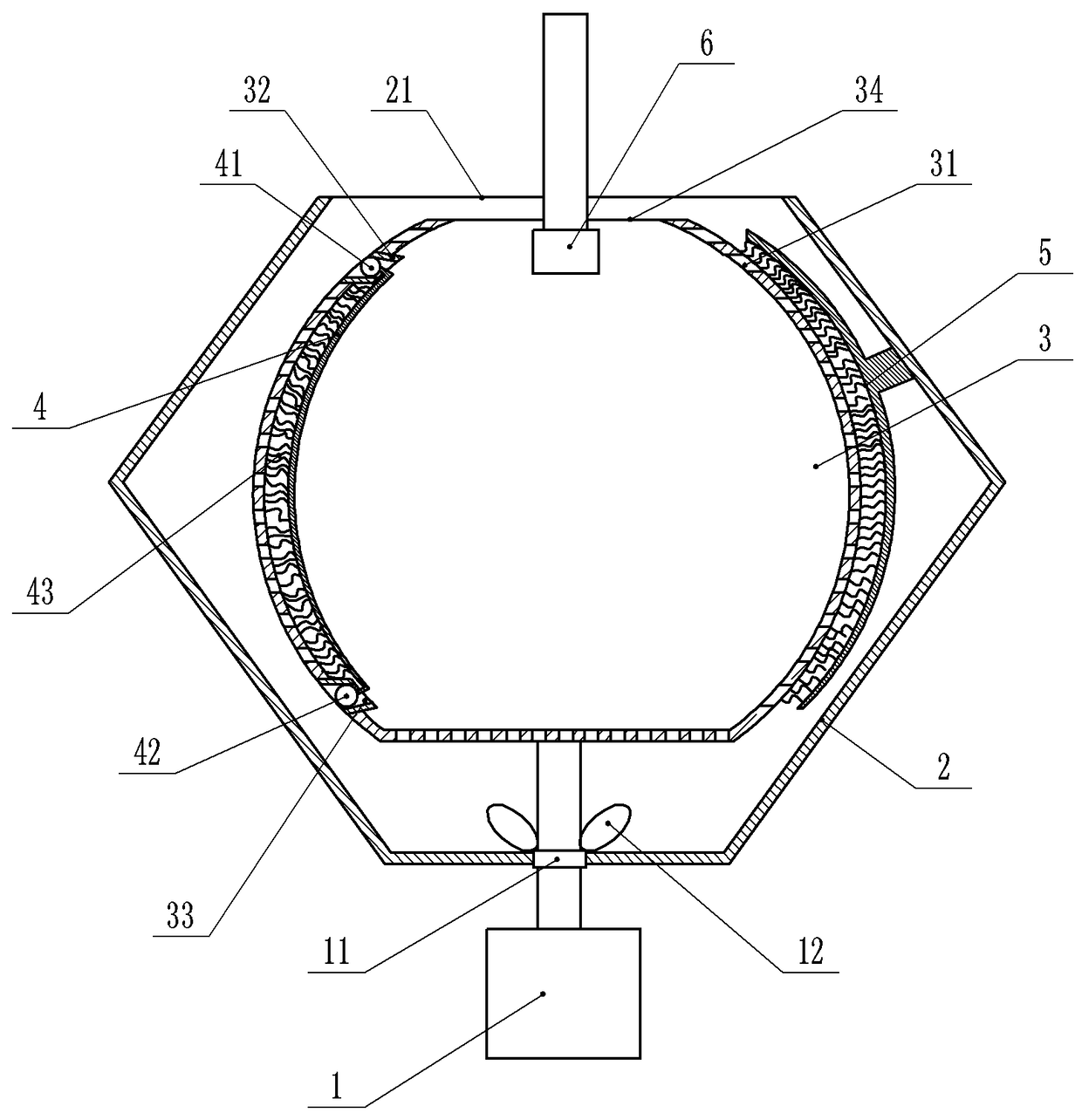
[0018] The reference signs in the accompanying drawings of the specification include: motor 1, bearing 11, blade 12, casing 2, exhaust port 21, liner 3, feed port 31, upper annular groove 32, lower annular groove 33, through hole 34, Brush rod 4, upper ball 41, lower ball 42, bristle 43, brush handle 5, nozzle 6.

[0019] Such as figure 1 As shown, a powder spraying machine for metal workpieces includes a nozzle 6, an inner tank 3, a cleaning brush, a casing 2 and a motor 1 from top to bottom, and the nozzle 6 is used to spray powder coated on the surface of a metal workpiece. The surface of the inner container 3 is provided with a plurality of through holes 34 , and the upper part of the inner container 3 is provided with a feeding port 31 through which metal workpieces are placed in the inner container 3 . The lower part of the housing 2 is conical, and the upper part...


PUM


Abstract

The invention belongs to the technical field of spraying devices, and particularly discloses a powder spraying machine used for metal workpieces. The powder spraying machine comprises an inner container, a shell, a cleaning brush, a motor and a sprayer; a feeding inlet is formed in the upper portion of the inner container, a plurality of through holes are formed in the surface of the inner container, an exhaust port is formed in the upper portion of the shell, and the inner container is located inside the shell; the sprayer is located above the inner container, the motor is installed below the shell, and an output shaft of the motor penetrates through the shell and is connected with the bottom of the inner container; a blade is arranged at the position, inside the shell, of the output shaft of the motor; the cleaning brush comprises an upper ball, a lower ball and a brush rod, and brush bristles are arranged on the brush rod; and an upper annular groove is formed in the upper portion of the inner wall of the inner container, a lower annular groove is formed in the lower portion of the inner wall of the inner container, the upper ball is connected into the upper annular groove in a sliding mode, and the lower ball is connected into the lower annular groove in a sliding mode. The powder spraying machine is used for spraying powder to the metal workpieces and can evenly spray the power to each surface of the metal workpieces, residual powder can be effectively recovered in the process, and the spraying quality is good.

Description

technical field [0001] The invention belongs to the technical field of spraying devices, in particular to a powder spraying machine for metal workpieces. Background technique [0002] Metal surface treatment - powder coating, is a method of protecting metal from oxidation and corrosion. The corrosion phenomenon that occurs around us refers to the damage, performance degradation or deterioration of the state of various materials under the action of the environment (the combination of chemical, electrochemical and several physical factors), while spraying paint on the metal surface is a A very important means of metal corrosion protection. A good spray protection layer can be well combined with metal workpieces and can inhibit the intrusion of corrosive media. The corrosion of powder-coated metal has a lot to do with the corrosion resistance of the metal material itself. Metals used for spray-painted coatings include steel materials, aluminum alloys, copper alloys or magnesi...

Claims


Application Information

Patent Timeline
Patent Type & Authority Patents(China)
IPC IPC(8): C23C24/02
CPCC23C24/02
Inventor 嵇建斌胡光强胡筱
Owner ZUNYI ZHONGBO CEMENTED CARBIDE
Learn More