Novel LED lamp

An LED lamp, a new type of technology, applied in lighting and heating equipment, semiconductor devices of light-emitting elements, lighting devices, etc., can solve the problems of long assembly and disassembly time, accidental touch by installers, low work efficiency, etc., to achieve convenient repeatability Installation and use, prevention of electric shock accidents, and the effect of preventing accidental electric shocks

Inactive Publication Date: 2017-08-22
钟奇
View PDF8 Cites 4 Cited by
  • Summary
  • Abstract
  • Description
  • Claims
  • Application Information

AI Technical Summary

Problems solved by technology

Since the assembly and disassembly of the power supply part and the lighting part require tools such as screwdrivers, the assembly and disassembly takes a long time and the work efficiency is low, and the traditional LED lighting fixtures are directly connected to the lighting part through the exposed conductive sheet inside and outside the power supply part. It is easy to cause the installer to touch it by mistake, causing an electric shock hazard to the human body, and the safety performance is low

Method used


Image

  • Novel LED lamp
  • Novel LED lamp
  • Novel LED lamp

Examples


Embodiment Construction

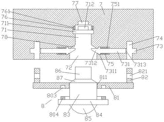
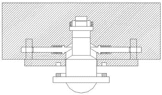
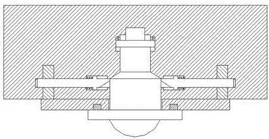
[0022] Such as Figure 1-Figure 5 As shown, a new type of LED lamp according to the present invention includes a power supply lamp holder 7 and an illuminating lamp 8 for cooperating with the power supply lamp holder 7, and a middle position inside the power supply lamp holder 7 is The first chute 71, the second chute 72 is provided under the bottom of the first chute 71, and the inner top wall of the power supply lamp holder 7 above the top of the first chute 71 is provided with a power supply groove 77, so The inner wall of the power supply lamp holder 7 on both sides of the first chute 71 is provided with a first guide chute 76, and a top pressure slider 711 is slidably connected in the first guide chute 76. The top of the slider 711 is provided with a conductive column 712 opposite to the power supply groove 77, and the top of the pressing slider 711 in the first guide chute 76 is provided with a first spring 761, and the first chute 71 and the second chute 72 are provide...


PUM


Abstract

The invention discloses a novel LED lamp which comprises a power supply lamp base part and a lighting lamp part used for being connected with the power supply lamp base part in a matched manner. A first sliding groove is formed in the middle portion of the interior of the power supply lamp base part, a second sliding groove is formed below the bottom of the first sliding groove, a power supply groove is formed in the position, above the top of the first sliding groove, of the top wall of the interior of the power supply lamp base part, first sliding guide grooves are formed in the positions, on the two sides of the first sliding groove, of the inner side wall of the power supply lamp base part, and ejection sliding blocks are connected to the interiors of the first sliding guide grooves in a sliding and matched manner; an electric conduction column is arranged at the tops of the ejection sliding blocks in a manner of being opposite to the power supply groove, first springs are arranged at the tops of the ejection sliding blocks in the first sliding guide grooves, and a taper face groove is arranged between the first sliding groove and the second sliding groove; and sliding locking holes are symmetrically arranged at the positions, on the two sides of the second sliding groove, in the power supply lamp base part, and second sliding guide grooves are formed in the positions, close to one side of the second sliding groove, of the sliding locking holes. The novel LED lamp is simple in structure, convenient to install, high in stability after installation and capable of preventing accidental electric shock and improving safety.

Description

technical field [0001] The invention relates to the technical field of LED lighting lamps, in particular to a novel LED lamp. Background technique [0002] Existing LED lighting fixtures for municipal roads are generally fixedly connected together by fasteners such as screws. During installation, tools such as screwdrivers are required to assemble the power supply unit and lighting unit together; when LED lighting fixtures fail, screwdrivers, etc. The tool disassembles the power supply part and the lighting part. Since the assembly and disassembly of the power supply part and the lighting part require tools such as screwdrivers, the assembly and disassembly takes a long time and the work efficiency is low, and the traditional LED lighting fixtures are directly connected to the lighting part through the exposed conductive sheet inside and outside the power supply part. It is easy to cause the installer to touch it by mistake, causing an electric shock hazard to the human bod...

Claims


Application Information

Patent Timeline
Patent Type & Authority Applications(China)
IPC IPC(8): F21S8/00F21V17/10F21V17/12F21V23/06F21V31/00F21Y115/10
CPCF21S8/00F21V17/10F21V17/12F21V23/06F21V31/005
Inventor 钟奇
Owner 钟奇
Why Eureka
Try Eureka