
Differential frequency conversion and amplitude modulation type eddy-current displacement sensor with high temperature self-following stepped-compensation characteristic

A displacement sensor, eddy current technology, applied in the direction of instruments, electrical devices, electromagnetic means, etc., can solve the problems of unsuitable displacement measurement sensors, such as molding products, to achieve accurate displacement measurement and reduce measurement errors.

Active Publication Date: 2017-08-22
BEIHANG UNIV
View PDF7 Cites 10 Cited by
  • Summary
  • Abstract
  • Description
  • Claims
  • Application Information

AI Technical Summary

Problems solved by technology

[0006] Currently in the market, the measurement range of the product is between -30°C and 175°C, and there is no displacement measurement sensor molding product suitable for a high temperature environment of 350°C

Method used


Image

  • Differential frequency conversion and amplitude modulation type eddy-current displacement sensor with high temperature self-following stepped-compensation characteristic
  • Differential frequency conversion and amplitude modulation type eddy-current displacement sensor with high temperature self-following stepped-compensation characteristic
  • Differential frequency conversion and amplitude modulation type eddy-current displacement sensor with high temperature self-following stepped-compensation characteristic

Examples


Embodiment Construction

[0033] Please refer to the accompanying drawings, and take circuit A as an example (wherein the circuit implementations of circuit A and circuit B are exactly the same), to further describe the present invention.

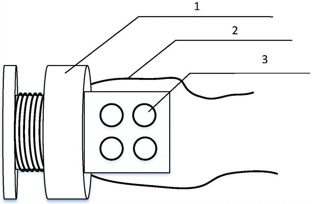
[0034] The invention provides a high temperature self-following graded compensation differential frequency conversion amplitude modulation eddy current displacement sensor, the probe part is as follows figure 1 As shown, it mainly includes winding skeleton and high temperature enameled wire. Among them, the high-temperature enameled wire uses polyimide as the insulating material, which can withstand 350°C. The outside of the coil is fixed by high-temperature glue, and TX500 high-temperature glue is selected. The coaxial cable uses F46 as the outer insulation material, and is fixed by high-temperature solder to connect with the probe coil.

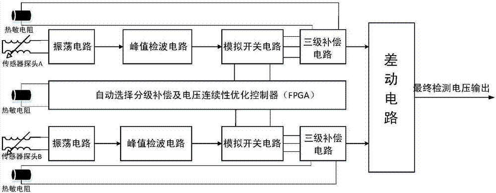
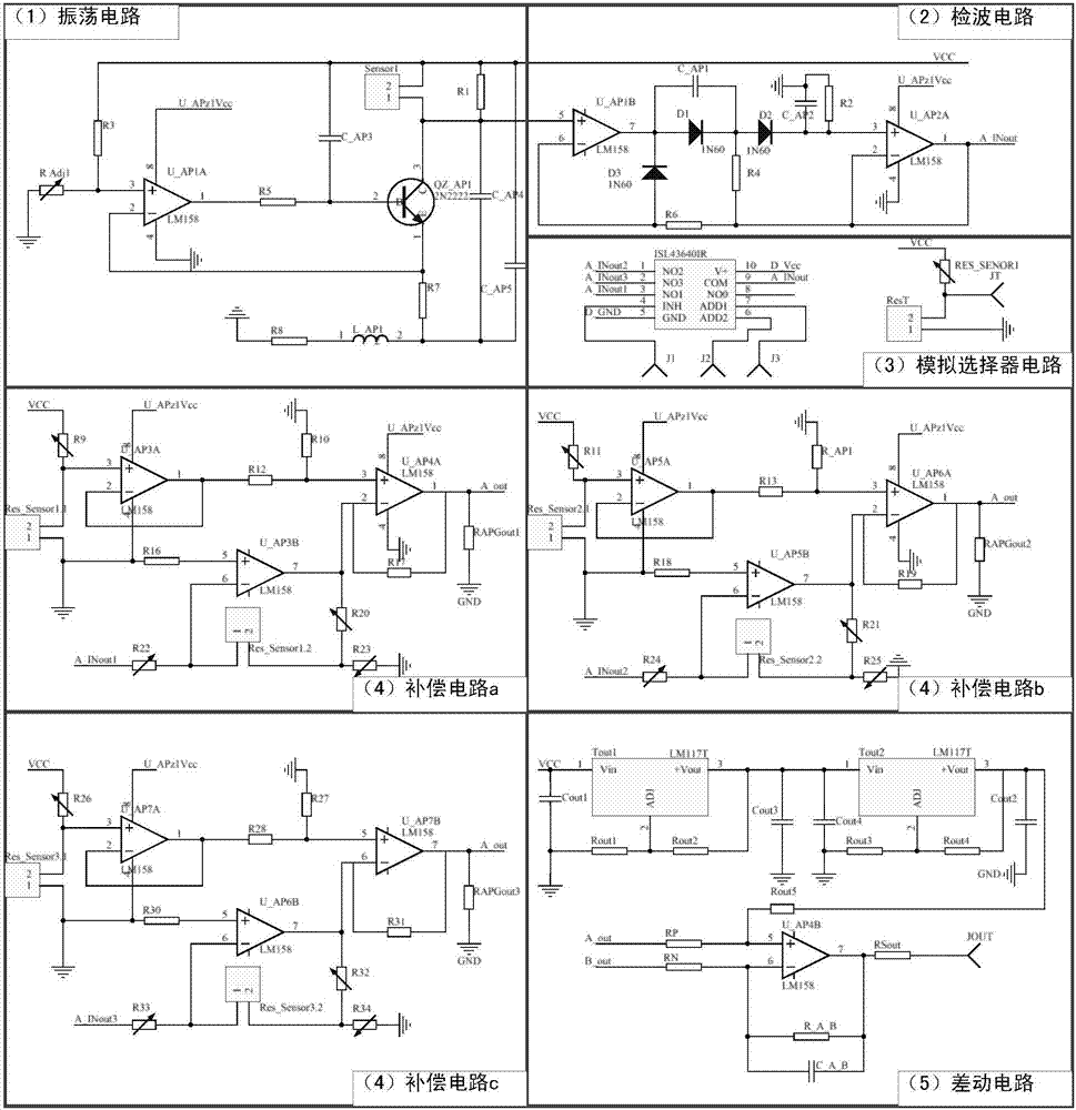
[0035] The sensor works as figure 2 and image 3 As shown, by the oscillation circuit ( image 3 The middle part (1)) gen...


PUM


Abstract

The invention, which belongs to the field of the eddy-current displacement sensor, discloses a differential frequency conversion and amplitude modulation type eddy-current displacement sensor with the high temperature self-following stepped-compensation characteristic. The sensor is composed of a probe, a temperature induction stepping circuit and a signal processing circuit. The probe is mainly composed of a coil, a high-temperature adhesive and a ceramic coil skeleton. The temperature signal processing circuit mainly consists of an oscillation circuit, a detection circuit, a filter, a three-stage linear compensation circuit and a differential circuit. The temperature induction stepping circuit includes a thermistor, an FPGA and an analog switch circuit. The single-path temperature drift situation of the eddy-current displacement sensor is collected on the condition of no compensation; a fitting resistance ratio of a multi-stage temperature drift compensation circuit is designed; the FPGA carries out controlling to select temperature compensation circuits at different levels; and then differential time drift error elimination is carried out at two paths with opposite moving directions of a measured object and then a final signal is outputted. The sensor is applied to a high-temperature magnetic suspension bearing.

Description

technical field [0001] The invention belongs to the field of eddy current displacement sensors, and relates to a detection circuit of a high temperature eddy current displacement sensor and a temperature drift compensation method thereof, so that it can automatically follow the temperature gradation compensation through a hierarchical compensation method according to the temperature drift phenomenon generated at different temperatures, Then, the error is eliminated twice through the two-way differential method to achieve high-precision high-temperature measurement. Background technique [0002] Eddy current displacement sensor is widely used as a non-contact displacement measurement method with large measurement range, high resolution and fast response. A common eddy current circuit is mainly composed of two parts: a probe and a signal processing circuit. The probe is mainly composed of an enameled wire coil and a coil frame, and the temperature signal processing circuit is...

Claims


Application Information

Patent Timeline
IPC IPC(8): G01B7/02
CPCG01B7/02
Inventor 郑世强刘希明韩邦成王坤张益明张利胜
Owner BEIHANG UNIV
Learn More