
Contact displacement meter

a technology of contact displacement and meter, which is applied in the direction of speed measurement using gyroscopic effects, instruments, surveying and navigation, etc., can solve the problems of inability to obtain correct measurement results, inability to read absolute position information, and inability to ensure sufficient measurement accuracy, etc., to achieve convenient detection and reliably read

Active Publication Date: 2010-11-02
KEYENCE
View PDF13 Cites 0 Cited by
  • Summary
  • Abstract
  • Description
  • Claims
  • Application Information

AI Technical Summary

Benefits of technology

[0014]The present invention has been devised to solve the problems described above, and an object thereof is to provide a contact displacement meter capable of performing an accurate displacement measurement even in a case where the movement speed of the contact is fast and having high resistance property to optical noise.
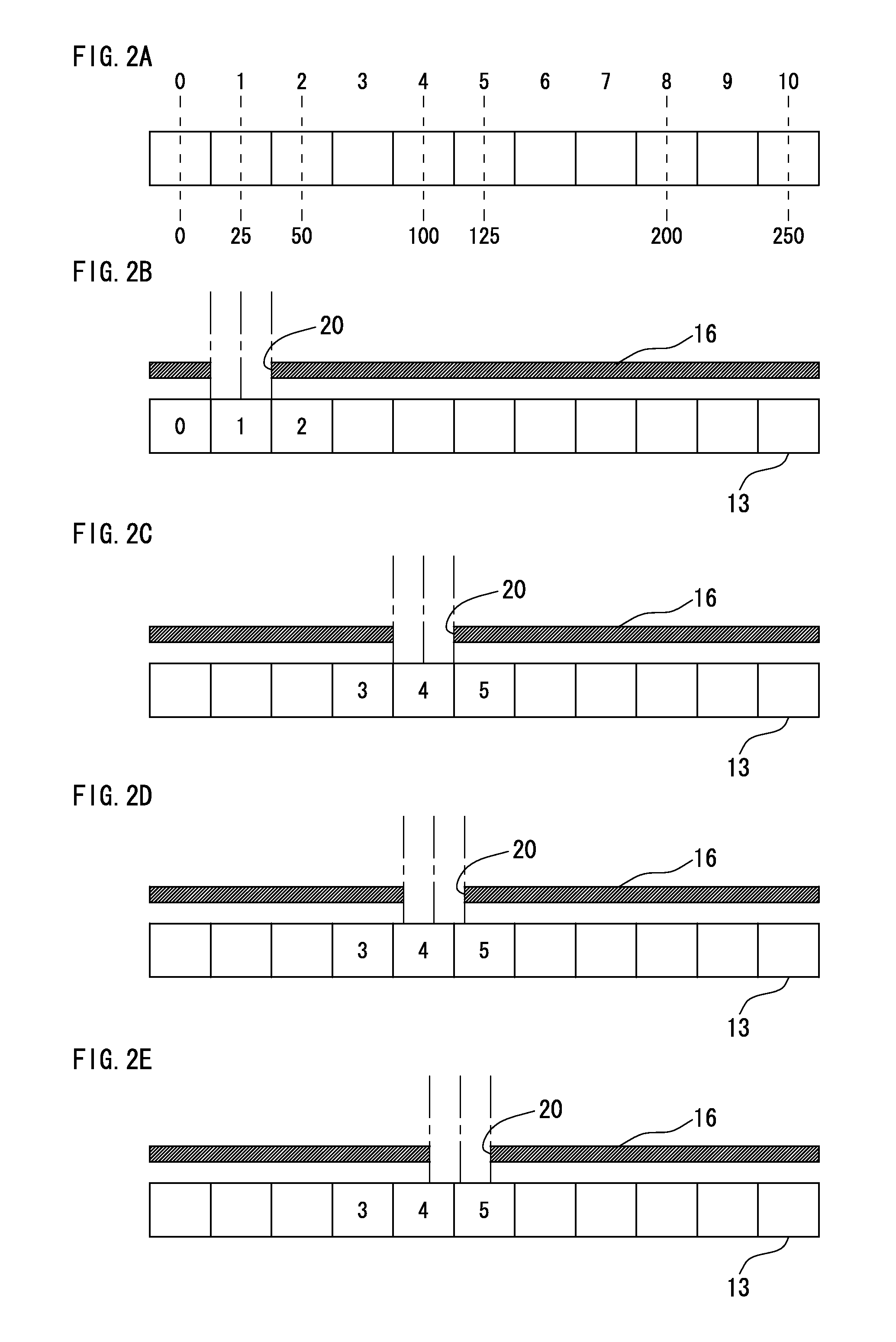
[0016]In the first invention, the adjacent reference light passing regions are away from each other by the distance of a unique value in the movement scale. The distance between the reference light passing regions is detected as a distance between the peak positions of the received light signal corresponding to the start bit or the received light signal of the light passed through the reference light passing region to specify an absolute position of the reference light passing region. The received light signal corresponding to the start bit is a steep pulse signal having one peak value, and thus the position of local maxim can be easily detected, and can be detected without being influenced by external noise. Therefore, the absolute position of the detected start bit can be specified by accurately detecting the distance between the start bits, and the absolute position can be reliably read even in a case where the contact is moved at fast speed.
[0019]In the second invention, the phase signal having the entire lattice region arrayed at the second array pitch as one cycle is obtained based on the received light signal of the light passed through the lattice region, and the relative position of the reference light passing region with respect to the line sensor is calculated. In other words, through the use of two scales having different pitches, a more detailed relative position can be accurately specified in addition to the absolute position defined based on the distance between the peak positions of the received light signal corresponding to the start bit.
[0021]In the third invention, the phase signal is obtained by performing discrete Fourier transformation in the zone of the extracted waveform, for example, based on the waveform of the envelope curve of greater than or equal to at least half a cycle contained in the received light signal, and the relative position can be reliably obtained using the portion of small noise even in a case where noise is contained.
[0026]According to the above-described configuration, the received light signal corresponding to the start bit is a steep pulse signal having one peak value, and thus the local maxim point can be easily detected, and can be detected without being influenced by external noise. Therefore, the absolute position of the detected start bit can be specified by accurately detecting the distance between the start bits, and the absolute position can be reliably read even in a case where the contact is moved at fast speed.

Problems solved by technology

However, if the contact is suddenly moved, miscounting of the scale pattern occurs, and a correct measurement result cannot be obtained.
However, it is difficult to have the light irradiated from the light source as a precise parallel light, and furthermore, even in a case where a precise parallel light is generated, unnecessary reflection occurs at the boundary edge portion of a light shielding region and a light passing region of the pattern, leakage light (or leakage charge) to the adjacent pixel occurs at the image sensor, and the like, and thus an ideal received light waveform as disclosed in Japanese Unexamined Patent Publication No. 2000-241115 is difficult to obtain.
Thus, the received light signal at the light receiving element includes various optical noises, reading of the absolute position information becomes difficult only from the received light signal of the light passed through the absolute position pattern and the precision optical lattice, and sufficient measurement accuracy cannot be ensured.
In the case of a Fourier image type as shown in Japanese Unexamined Patent Publication No. 05-346330, a diffraction phenomenon occurs with respect to the light passed through the fine absolute position pattern and the precision optical lattice, and thus an ideal received light waveform as disclosed in Japanese Unexamined Patent Publication No. 2000-241115 becomes difficult to obtain.
Thus, the received light signal at the light receiving element includes various optical noises, reading of the absolute position information becomes difficult only from the received light signal of the light passed through the absolute position pattern and the precision optical lattice, and sufficient measurement accuracy cannot be ensured.

Method used


Image

  • Contact displacement meter
  • Contact displacement meter
  • Contact displacement meter

Examples


first embodiment

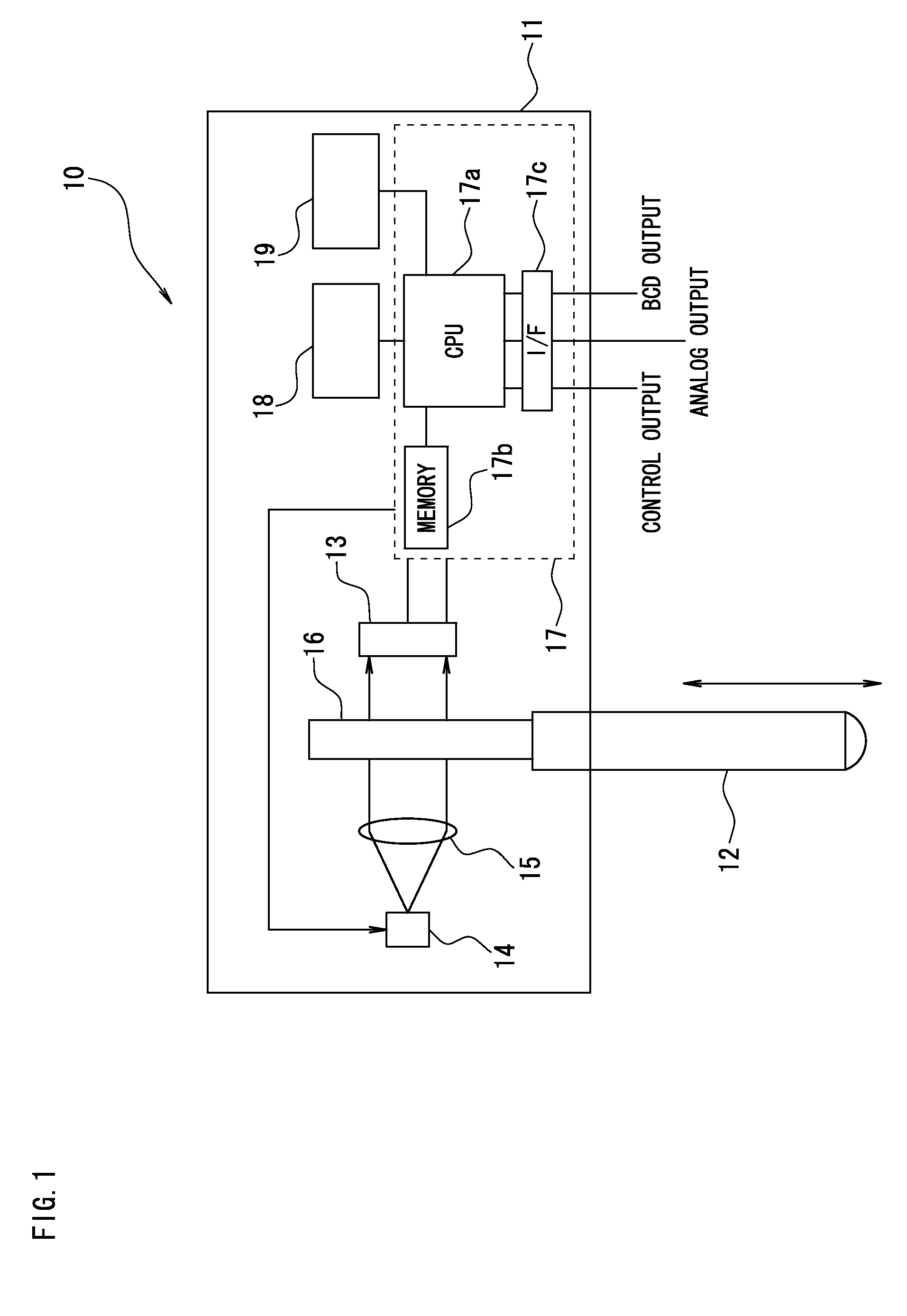
[0041]FIG. 1 is a block diagram showing a configuration of a contact displacement meter according to First Embodiment of the present invention. A contact displacement meter 10 according to First Embodiment includes a contact 12 movable in a predetermined direction inside a housing 11. The housing 11 has a substantially rectangular solid shape, which size is length×width×height of about 60 mm×30 mm×15 mm, and the relative displacement of the contact 12 in the length direction with respect to the housing 11 is measured.

[0042]The contact 12 is attached to the housing 11 so as to be linearly movable in a predetermined direction by way of a ball bearing, and the like. An elastic body such as a spring (not shown) for biasing the contact 12 in a projecting direction is arranged between the contact 12 and the housing 11. A light emitting element 14 is a light source such as an LED and an LD, where the light emitted from the light emitting element 14 is converted to a substantially parallel ...

second embodiment

[0095]FIG. 11 is a block diagram showing a configuration of a contact displacement meter according to Second Embodiment of the present invention. FIG. 11 differs from the block diagram shown in FIG. 1 only in that a fixed scale 30 in which light passing regions and light shielding regions are alternately arrayed at substantially equal intervals in one direction is arranged on the optical path from the movement scale 16 to the line sensor 13. A periodic light receiving dead band is consequently formed on the line sensor 13 by the light shielding regions in the fixed scale 30. Therefore, the light receiving element is sandwiched by the light receiving dead band, and thus one light receiving element receives only the light passed through one light passing region.

[0096]To prevent variation of the measurement value, similar to First Embodiment, one light receiving element is divided to the lower side and the upper side, and correction is made similar to First Embodiment as the lower side...


PUM


Abstract

A contact displacement meter capable of performing an accurate displacement measurement where a movement speed of a contact is fast and having high resistance property to optical noise. A reference light passing regions are away from each other by a distance of a unique value in a movement scale. A peak position of the reference light passing region at which a received light signal of light passed through the reference light passing region takes a local maxim is detected, and an absolute position of the reference light passing region is specified based on the distance between the adjacent peak positions. A relative position of the reference light passing region with respect to a line sensor is specified based on a received light signal of light passed through a lattice region. A displacement of the contact is calculated based on the specified absolute position and the relative position.

Description

CROSS-REFERENCE TO RELATED APPLICATIONS[0001]The present application claims foreign priority based on Japanese Patent Application No. 2008-079241, filed Mar. 25, 2008, the contents of which is incorporated herein by reference.BACKGROUND OF THE INVENTION[0002]1. Field of the Invention[0003]The present invention relates to contact displacement meters, in particular, to an optical absolute type contact displacement meter for reading a relative displacement of a built-in scale with a line sensor.[0004]2. Description of the Related Art[0005]The contact displacement meter includes a contact attached so as to be movable with respect to a housing, and measures the displacement of a measuring object by contacting the contact to the measuring object and measuring the relative displacement of the contact with respect to the housing with a detector incorporated in the housing. The detector incorporated in the housing may be configured by a magnet and a differential transformer, may be configure...

Claims


Application Information

Patent Timeline
Patent Type & Authority Patents(United States)
IPC IPC(8): G06F15/00G01B11/14
CPCG01B11/026G01D5/34746G01D5/34761
Inventor FUJIMOTO, SUKETAKA
Owner KEYENCE
Learn More