Optical bench

A technology of optical bench and pedestal, which is applied in the field of physical experiments and can solve problems such as the difficulty of moving at a uniform speed

Inactive Publication Date: 2019-04-09
周峙
View PDF5 Cites 1 Cited by
  • Summary
  • Abstract
  • Description
  • Claims
  • Application Information

AI Technical Summary

Problems solved by technology

[0004] The disadvantage of the existing technology is that due to the certain inertia of the sliding connection, it is difficult to move the fixed part on the slide rail at a uniform speed during the experiment, such as moving the fixed part from 5cm to 7cm at a constant speed to observe the change of the image. It is difficult to move at a constant speed; on the other hand, it is difficult to move the fixing part to the target position in one step. If the fixing part needs to be slid to 5.4cm, due to the inertia, the fixing part will often be moved to between 5.3cm-5.5cm for the first time. It needs to be adjusted once or twice to reach 5.4cm

Method used


Image

  • Optical bench
  • Optical bench
  • Optical bench

Examples


Embodiment Construction

[0033] In order to enable those skilled in the art to better understand the technical solutions of the present invention, the present invention will be further described in detail below in conjunction with the accompanying drawings.

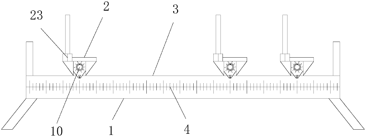
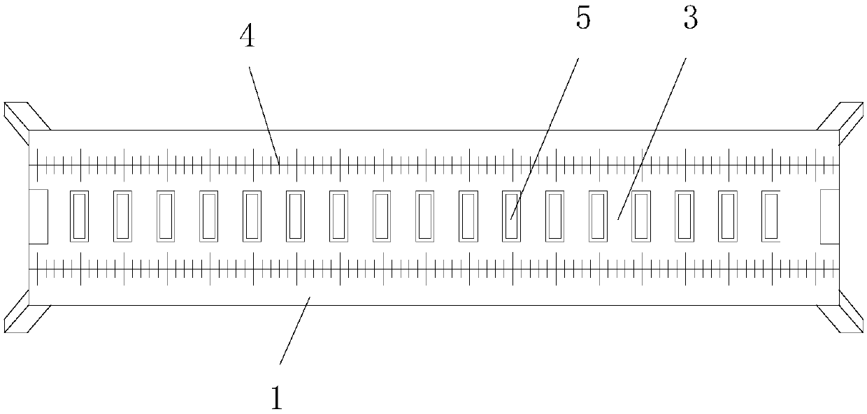
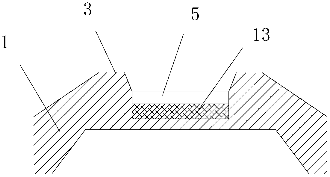
[0034] Such as Figure 1-7 As shown, an optical bench provided by an embodiment of the present invention includes a base 1 and a plurality of fixtures 2 for installing experimental components, and the base 1 is provided with a connection surface extending along a first direction 3. The base 1 is provided with a first scale 4 along the connecting surface 3, and the connecting surface 3 is provided with a plurality of first socket parts 5 evenly spaced, and the fixing member 2 is provided with a first scale 4. Two plug-in parts 6, the first plug-in part 5 of each said fixing part 2 can be mated with any second plug-in part 6; The rack 8 and the fixed block 9, the transmission rod runs through the housing 7, the end of the transmission rod located ...


PUM


Abstract

The invention discloses an optical bench, which includes a base and a plurality of fixing parts for installing experimental components, the base is provided with a connection surface extending along a first direction, and the base is provided with a connection surface along the connection surface. For the first scale, a plurality of first plug-in parts are evenly spaced on the connecting surface, and second plug-in parts are arranged on the fixing part, and the first plug-in parts of each fixing part can be plugged with any second plug-in parts Cooperate; one end of the transmission rod on the outside of the housing is connected with a knob, the transmission rod is connected to a gear on the inside of the housing, the gear and the rack are meshed, and the fixed block is fixedly connected to the rack; the housing is surrounded by a knob As for the second scale, the distance between two adjacent first plug joints is not greater than the distance that the transmission rod rotates to drive the fixed block to move, and the first scale is an order of magnitude larger than the second scale. The optical bench provided by the present invention is not only easy to rotate at a constant speed when the knob connected to the gear is controlled, but also can be rotated to the target position more conveniently at one time.

Description

technical field [0001] The invention relates to physical experiment technology, in particular to an optical bench. Background technique [0002] Middle school physics experiments involve many optical experiments, such as convex lens experiment, concave lens experiment, small hole imaging experiment, etc. The experimental equipment of these optical experiments includes optical bench, and each optical experimental component is installed on the optical bench to complete the corresponding experiment. [0003] The inventor found in the usual study and research that in the prior art, the optical bench includes a base, and a slide rail is arranged on the base, and a plurality of fixing parts for fixing the optical experiment elements are slidably connected to the slide rail. During the experiment, the Different experimental components are fixed to each fixture one by one, and after the light source is turned on, the fixtures are slid back and forth on the slide rail to obtain the ...

Claims


Application Information

Patent Timeline
Patent Type & Authority Patents(China)
IPC IPC(8): G02B7/00
CPCG02B7/00
Inventor 周峙
Owner 周峙
Why Eureka
Try Eureka