
Anti-overspeed belt conveyor

A technology for belt conveyors and conveyor belts, which is applied in the direction of conveyors, conveyor objects, conveyor control devices, etc., and can solve problems such as speeding accidents, waste, and speed out of control

Inactive Publication Date: 2020-10-20
湖南零陵恒远发电设备有限公司
View PDF0 Cites 2 Cited by
  • Summary
  • Abstract
  • Description
  • Claims
  • Application Information

AI Technical Summary

Problems solved by technology

The conveying device often has its rated speed, which is limited to run at a certain speed. If it runs above the speed, it will cause damage, cause excessive conveying volume, cause blockage, and throw materials out, resulting in waste, because most of these belt conveyors Using a motor, the speed of the motor will be changed by factors such as frequency and voltage. When the frequency converter fails or is damaged, the speed will be out of control and a speeding accident will occur.
[0003] In the existing technology, some use sensors to detect the speed. When the speed is too high, the controller controls the motor to run at a reduced speed. The stability of this technology is not high enough. In the harsh environment of high temperature and high pressure, sensors, lines, Components such as the controller are easily damaged and malfunctioned. Therefore, a belt conveyor that can effectively prevent overspeed is needed

Method used


Image

  • Anti-overspeed belt conveyor
  • Anti-overspeed belt conveyor
  • Anti-overspeed belt conveyor

Examples


Embodiment approach 1

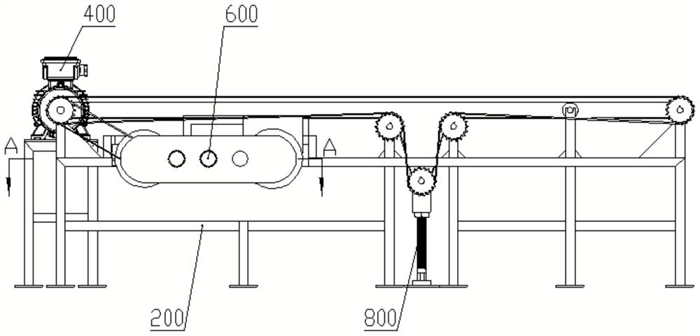
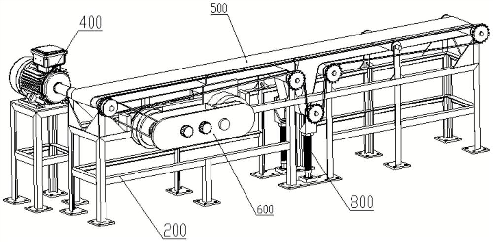
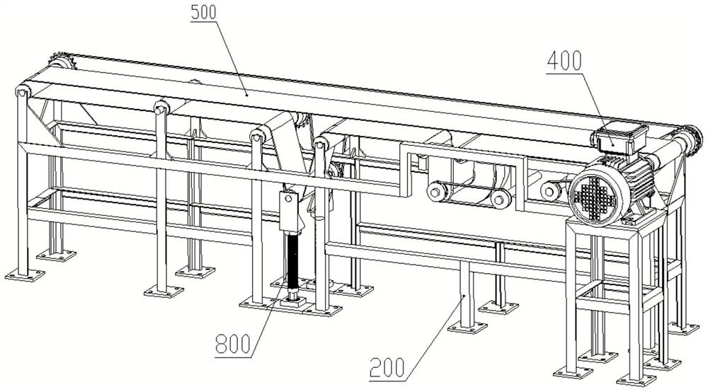
[0113] Such as Figure 1-16 As shown, this embodiment provides an anti-overspeed belt conveyor, including:

[0114] frame body 200;

[0115] There are at least two belt rollers 700, which are rotatably connected with the frame body 200;

[0116] The conveying belt 500 is wound on the belt roller 700 and is used for conveying materials;

[0117] The driving mechanism 400 is connected with the conveying belt 500 and is used to drive the conveying belt 500 to rotate;

[0118] The roller speed limiting mechanism 100 is connected with the belt roller 700 to prevent the belt roller 700 from running at an overspeed;

[0119] The speed-regulating operating mechanism 600 is connected with the roller speed-limiting mechanism 100 and is used to adjust the running resistance of the roller speed-limiting mechanism 100;

[0120] The belt adjustment mechanism 800 is connected with the conveying belt 500 and used for adjusting the tension of the conveying belt 500 .

[0121] Among them, ...

Embodiment approach 2

[0180] refer to Figure 17-Figure 21 The main difference between this embodiment and Embodiment 1 is that the roller speed limiting mechanism 100 uses a uniform speed mechanism 130 and an adjusting mechanism 140 of different structures, while the frame body 200, the belt roller 700, the conveyor belt 500, the driving mechanism 400, and the roller limiter The housing 110 of the speed mechanism 100, the arrangement of non-Newtonian fluid, the connection of the rotating shaft 120, and the stirring working principle and beneficial effect of the first stirring blade 135 are all the same as those of Embodiment 1, and the differences will be described in detail below.

[0181] The constant speed mechanism 130 of this embodiment adopts two radially evenly distributed first stirring blades 135, which also includes:

[0182] The sliding sleeve 131 is sleeved on the rotating shaft 120, and the sliding sleeve is provided with a chute 136;

[0183] The slider 132 is embedded in the chute ...


PUM


Abstract

The invention discloses an anti-overspeed belt conveyor. The anti-overspeed belt conveyor comprises a frame body, belt rollers, a conveying belt, a driving mechanism, a belt adjusting mechanism, a roller speed limiting mechanism and a speed adjusting operation mechanism, wherein the belt roller is rotatably connected with the frame body, and the conveying belt is wound on the belt roller. The driving mechanism is connected with the conveying belt and used for driving the conveying belt to rotate. The roller speed limiting mechanism is connected with the belt roller and used for preventing thebelt roller from overspeed running. The speed adjusting operation mechanism is connected with the roller speed limiting mechanism and is used for regulating the running resistance of the roller speedlimiting mechanism. The belt adjusting mechanism is connected with the conveying belt and used for adjusting the tension degree of the conveying belt. By means of the anti-overspeed belt conveyor, itcan be guaranteed that the conveying device does not rotate in an overspeed mode, unnecessary losses caused by overspeed are avoided, and the anti-overspeed belt conveyor can safely and stably operateeven in a high-temperature and high-pressure severe environment and can be widely applied to various occasions needing speed limiting.

Description

technical field [0001] The invention relates to a conveying device, in particular to an anti-overspeed belt conveyor. Background technique [0002] Belt conveyor is a kind of conveying device, which is a device for transporting materials from one place to another. It is widely used in mining, metallurgy, building materials, chemical industry, electric power, ports, food processing and other industrial fields to convey Various materials. These conveying devices must rely on electric motors or other power to drive their operation. The conveying device often has its rated speed, which is limited to run at a certain speed. If it runs above the speed, it will cause damage, cause excessive conveying volume, cause blockage, and throw materials out, resulting in waste, because most of these belt conveyors Using a motor, the speed of the motor will be changed by factors such as frequency and voltage. When the frequency converter fails or is damaged, the speed will be out of control...

Claims


Application Information

Patent Timeline
IPC IPC(8): B65G23/30B65G23/22B65G43/00
CPCB65G23/22B65G23/30B65G43/00B65G2203/0291
Inventor 郭远军郭幸铜郭幸钢
Owner 湖南零陵恒远发电设备有限公司
Learn More