Air volume adjusting plate for plug-in box, and application method thereof

A technology of air volume adjustment and application method, which is applied in the direction of cooling/ventilation/heating transformation, electrical components, electrical equipment construction parts, etc., and can solve problems such as increased use cost and equipment cost, reduced module performance, and increased fan power consumption. Achieve the effects of reducing the cost of the subrack, balancing noise and power consumption, and improving heat dissipation efficiency

Active Publication Date: 2017-08-22
成都特锐泰雷兹电子应用科技有限公司
View PDF10 Cites 5 Cited by
  • Summary
  • Abstract
  • Description
  • Claims
  • Application Information

AI Technical Summary

Problems solved by technology

The use of the existing heat dissipation structure and the heat dissipation method of evenly distributing the ventilation volume will lead to insufficient ventilation of some modules with high heat generation. After a long time of operation, the temperature of the module exceeds the allowable temperature, and it is easy to reduce the performance of the module or even damage it.
[0006] For this situation, the conventional solution adopted in this field is mainly to increase the total ventilation volume generated by the fans so that the average ventilation volume allocated to each module can meet the heat dissipation demand of the module with the largest heat generation, that is, according to The calorific value of the module with the largest calorific value is multiplied by the number of modules as the total calorific value to calculate the total ventilation required, which will lead to a large redundancy in the ventilation. Produce more noise, the corresponding use cost and equipment cost will increase

Method used


Image

  • Air volume adjusting plate for plug-in box, and application method thereof
  • Air volume adjusting plate for plug-in box, and application method thereof
  • Air volume adjusting plate for plug-in box, and application method thereof

Examples


Embodiment

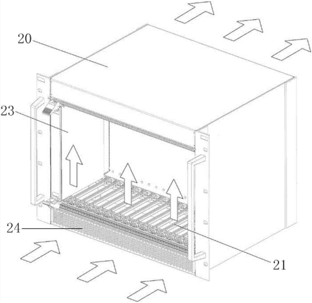
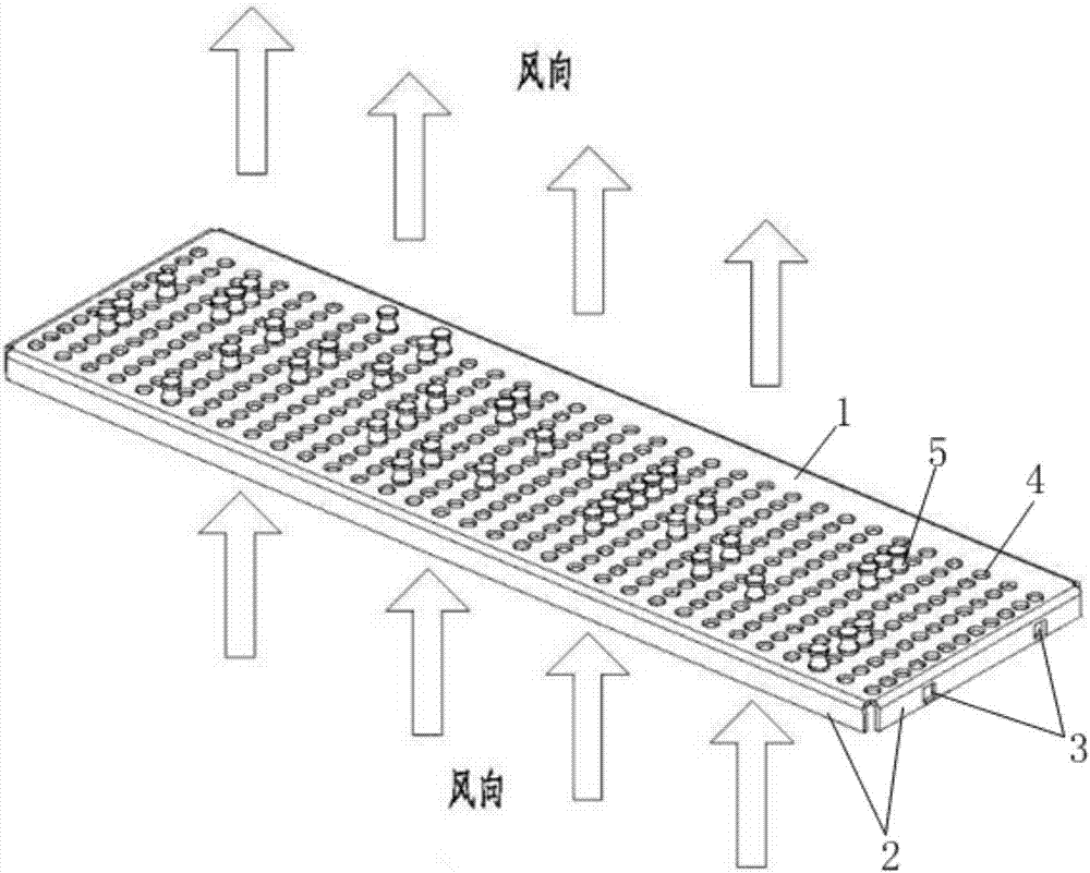
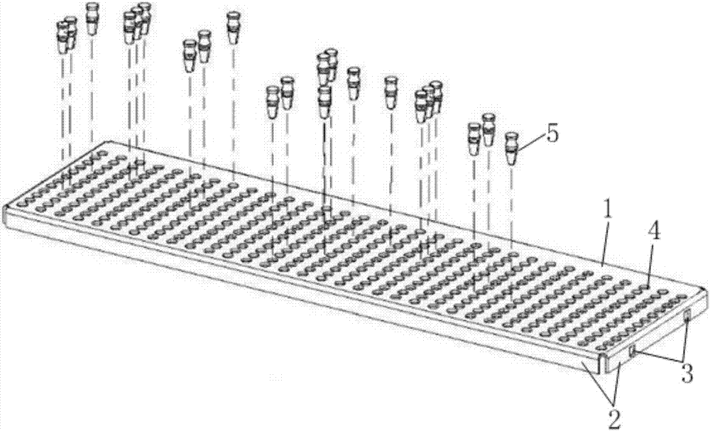
[0038] Such as Figure 2 to Figure 6 As shown, the air volume adjustment plate is mainly used in subracks, and specifically includes a plate body 1 matching the shape of the bottom of the subrack, a connecting part 2 arranged on the side of the panel, and opened on the connecting part for connecting the subracks. port 3, a plurality of ventilation holes 4 opened on the board and arranged regularly, and a plurality of plugs 5 respectively inserted in different ventilation holes for changing the ventilation volume at different positions on the board. In this embodiment, the ventilation holes are regularly arranged in a 12×32 matrix, that is, 12 ventilation holes are arranged in a row, and a total of 32 rows are arranged in parallel. The spacing between the 12 ventilation holes in the row can be relatively close, and the spacing between the ventilation holes in each row matches the gap between the guide rails in the subrack, ensuring that the gap between each guide rail correspon...


PUM


Abstract

The invention discloses an air volume adjusting plate for a plug-in box. The air volume adjusting plate comprises a plate body matching the shape of the bottom of the plug-in box; a connection portion disposed on a side surface of the plate body; a connection port disposed on the connection portion and to be connected with the plug-in box; a plurality of vent holes arranged on the plate body regularly; and latches inserted into different vent holes and used for changing the air volume at different positions on the plate body. All the vent holes are arranged in parallel on the plate body in a plurality of rows. Each gap between guide rails in the plug-in box corresponds to at least one row of vent holes. The invention also discloses the application method of the air volume adjusting plate. The air volume adjusting plate ingeniously changes the air volume of different functional modules by the arrangement of the latches on the plate body. Thus, each module is ventilated and cooled on demand, the air volume of respective modules are reasonably distributed, the heat dissipation efficiency of a draught fan is improved, the cost of plug-in box is reduced integrally, and a good balance is made between the air volume and draught fan noise and power consumption. The air volume adjusting plate is ingenious in design, simple in structure, and easy to use.

Description

technical field [0001] The invention relates to a box insertion component, in particular to an air volume regulating plate for a box insertion and an application method thereof. Background technique [0002] A subrack, also known as a U box, is a standard chassis that is widely used in structural cabinets such as communication cabinets, power cabinets, and CPCI (Compact Peripheral Component Interconnect, Compact PCI). There are multiple guide rails arranged side by side in the lower part of the box for plugging and installing various functional modules. This standardized module installation and plugging method is favored by users because of its convenience. And because the modules in the subrack are installed side by side, there will be no problem of obstructed air circulation caused by various boards blocking each other in the ordinary chassis. In contrast, the heat dissipation performance of the subrack is relatively excellent. [0003] With the development of science and...

Claims


Application Information

Patent Timeline
Patent Type & Authority Applications(China)
IPC IPC(8): H05K7/20
CPCH05K7/20145
Inventor 张进严志坚
Owner 成都特锐泰雷兹电子应用科技有限公司
Why Eureka
Try Eureka