
Attached type self-lifting derrick

A self-lifting and attached technology, applied in towers, building types, buildings, etc., can solve problems such as affecting the construction safety of transmission line towers, restricting the normal use of external cables, and difficulty in one-time installation of poles. Increased flexibility and accurate positioning

Pending Publication Date: 2017-08-25
STATE GRID CORP OF CHINA +4
View PDF10 Cites 12 Cited by
  • Summary
  • Abstract
  • Description
  • Claims
  • Application Information

AI Technical Summary

Problems solved by technology

However, during the use of the tower with inner suspension and outer guy wires, the control requirements for the outer guy wires in the outer guy wire system are extremely strict, and the complex terrain environment in mountainous areas easily limits the normal use of the outer guy wires in the outer guy wire system
For example, the complex terrain of mountainous areas can allow the extension distance of the outer stay wires to be limited. When the outer stay wires are installed on the poles, the suspension of the stay poles in the center of the transmission line tower truss cannot be successfully completed at one time by using the outer stay wires. It is difficult to install the pole in place at one time by using the outer stay wire in the limited terrain, and the fixed end of the outer stay wire on the ground can only fall in the area close to the tower body of the transmission line, so that the outer stay wire is on the ground The force on the fixed end of the transmission line tower is also relatively large, and there is a large construction risk, which is likely to affect the construction safety of the transmission line tower

Method used


Image

  • Attached type self-lifting derrick
  • Attached type self-lifting derrick
  • Attached type self-lifting derrick

Examples


Embodiment Construction

[0038] For ease of understanding, the attached pole provided by the embodiment of the present invention will be described in detail below with reference to the accompanying drawings.

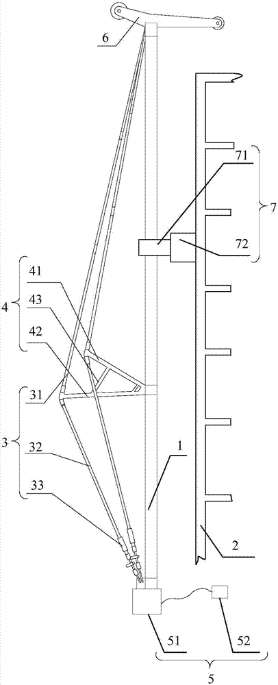
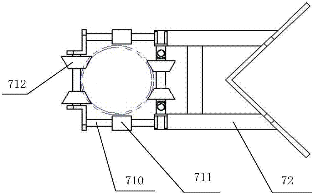
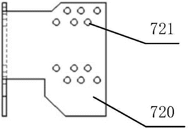
[0039] see figure 1 and figure 2 , the attached self-elevating pole provided by the embodiment of the present invention includes a pole 1, the bottom of the pole 1 is provided with a self-elevating device 5 for lifting the pole, and the top of the pole 1 is provided with a tower member for lifting the transmission line tower 2 The lifting device 6; wherein, the attached self-elevating pole also includes at least one guide device 7 for guiding the lifting of the pole 1, and the guide device 7 includes a mounting part 72 and a positioning guide part fixedly connected with the mounting part 72 71, the installation part 72 can be fixedly connected with the transmission line tower 2; the positioning guide part 71 includes a positioning frame 710 fixedly connected with the installation part 72, and ...


PUM


Abstract

The invention discloses an attached type self-lifting derrick, relates to the technical field of special equipment for power transmission line construction and is used for reducing the safety risk when a power transmission line tower is assembled and constructed in a mountainous area. The attached type self-lifting derrick comprises a derrick body, wherein a self-lifting device for lifting the derrick body is arranged at the bottom of the derrick body, and a hoisting device for hoisting tower material components of the power transmission line tower is arranged at the top of the derrick body; the attached type self-lifting derrick further comprises at least one guide device for guiding lifting of the derrick body, the guide device comprises a mounting part and a positioning guide part fixedly connected with the mounting part, and the mounting part can be fixedly connected with the power transmission line tower; the positioning guide part comprises a positioning frame fixedly connected with the mounting part, and multiple groups of guide pulleys for guiding lifting of the derrick body are arranged on the positioning frame. The attached type self-lifting derrick is used for assembling and constructing the power transmission line tower.

Description

technical field [0001] The invention relates to the technical field of special equipment for transmission line construction, in particular to an attached self-elevating pole. Background technique [0002] The most common tower assembly method in the construction of transmission line towers is the internal suspension and external stay wire tower assembly method, which mainly uses the already assembled transmission line tower body, through the support system and the external stay wire system, so that the pole is suspended on the The truss center of the transmission line tower body, and then the transmission line tower components are hoisted sequentially through the lifting system installed on the pole to complete the assembly of the transmission line tower. [0003] At present, with the continuous construction of power transmission and transformation projects, the construction of transmission line towers will inevitably be carried out in mountainous areas. However, during the...

Claims


Application Information

Patent Timeline
IPC IPC(8): E04H12/34
CPCE04H12/34
Inventor 熊织明肖贵成李松王海超吕素萌侯镭王小松罗本壁高晓莉杨作强张超
Owner STATE GRID CORP OF CHINA
Learn More