Fresh air system capable of enabling fresh air to flow along with human body and using method thereof

A fresh air system, fresh air technology, applied in ventilation and heating energy recovery systems, ventilation systems, heating and ventilation control systems, etc. Humidity ratio and other issues to achieve the effect of noise reduction

Inactive Publication Date: 2017-08-25
张在东
View PDF8 Cites 3 Cited by
  • Summary
  • Abstract
  • Description
  • Claims
  • Application Information

AI Technical Summary

Problems solved by technology

At present, fan coil units are mostly used to control temperature and humidity, but fan coil units are difficult to adapt to changes in indoor heat-humidity ratio, and often reduce the control of humidity to meet the requirements of room temperature. The processing of a certain item will inevitably affect the change of another item
In this way, it is difficult to achieve the balance of indoor temperature and humidity, which affects the comfort of the indoor environment.

Method used


Image

  • Fresh air system capable of enabling fresh air to flow along with human body and using method thereof
  • Fresh air system capable of enabling fresh air to flow along with human body and using method thereof
  • Fresh air system capable of enabling fresh air to flow along with human body and using method thereof

Examples


Embodiment 1

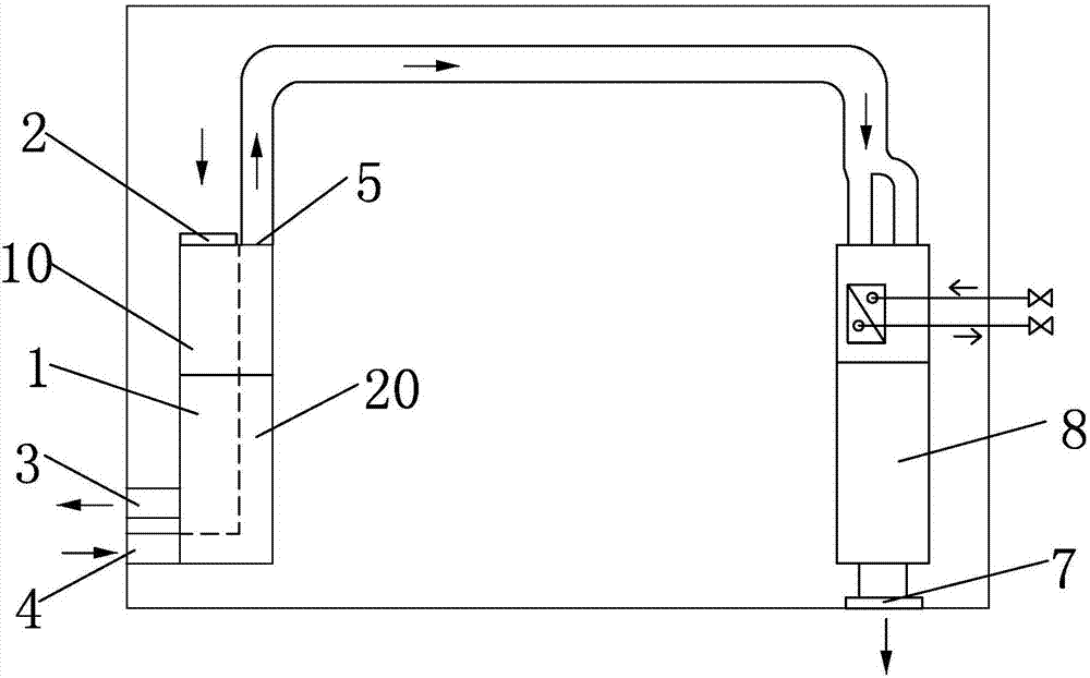
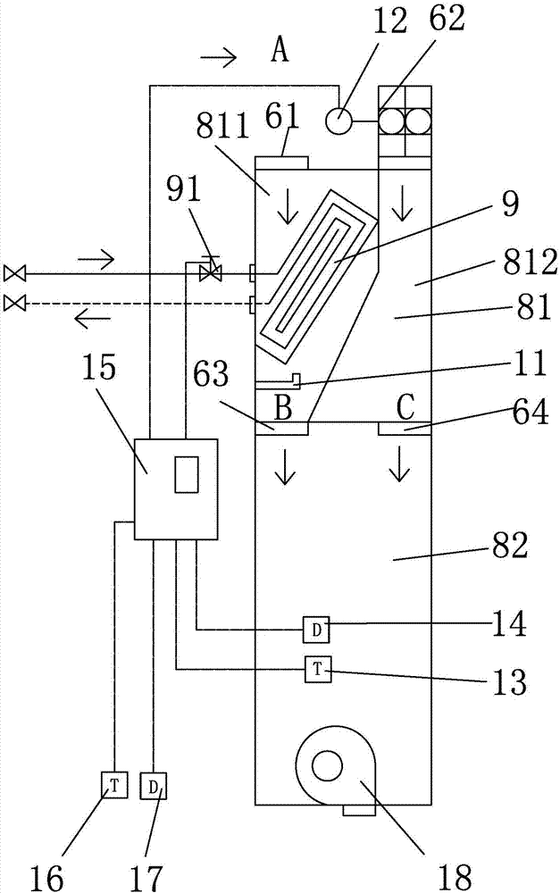
[0035] Such as figure 1A fresh air system shown in , which can make the fresh air follow the human body, includes a clean heat recovery fresh air unit 1 , which has an exhaust air inlet 2 , an exhaust air outlet 3 , a fresh air inlet 4 , and a fresh air outlet 5 . Among them, the exhaust air inlet 2 to the exhaust air outlet 3 form an exhaust air passage 10 for discharging indoor air to the outside, and the fresh air inlet 4 and fresh air outlet 5 form a fresh air passage 20 for outdoor air to enter the room. The fresh air outlet 5 is connected to the air inlet of the dehumidification temperature control machine through a pipeline, and the air outlet 7 of the dehumidification temperature control machine is connected to the ground air supply pipeline in the communication room. Described dehumidification temperature controller 8 (as figure 2 shown in ), has an air inlet section 81 and an air conditioning section 82, wherein the air inlet section 81 includes two air inlet passa...

Embodiment 2

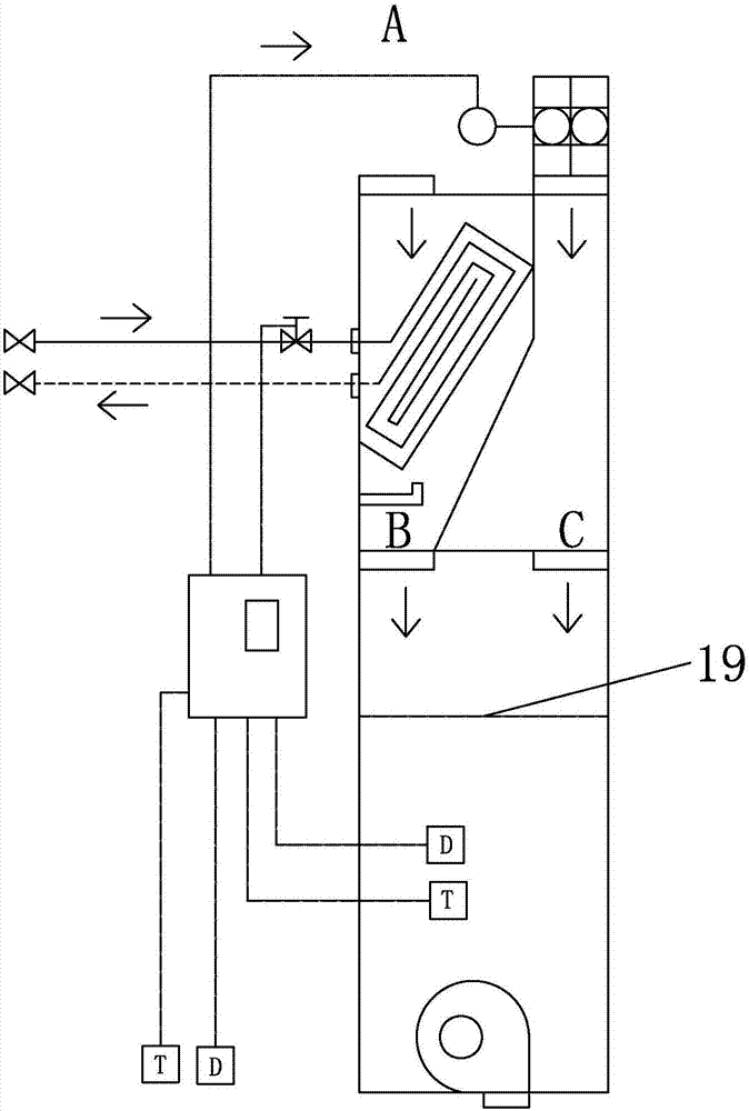
[0040] Furthermore, especially in summer, due to the high humidity in the outdoor air, in order to achieve the appropriate humidity, the dew point temperature of the cold water coil will be lowered, and the temperature of the mixed fresh air will be lower. Only by adjusting the air flow of C Can not satisfy temperature requirement, therefore, on the structural basis of embodiment 1, be provided with auxiliary heater 19 in the regulating air section 82 of dehumidification temperature control machine 8, as image 3 shown in . The auxiliary heater 19 in this embodiment is an electric heater. When the temperature cannot meet the requirements by adjusting the air in the C circuit, the unit controller controls the auxiliary heater to start heating.

Embodiment 3

[0042] Furthermore, in order to avoid that the humidity adjustment cannot meet the requirements, on the basis of the structure of Embodiment 2, an auxiliary humidifier 30 is provided in the air conditioning section 82 of the dehumidification temperature controller 8, wherein the auxiliary humidifier 30 is arranged in the auxiliary heating top of device 19, as Figure 4 shown in . The installation positions of the auxiliary humidifier 30 and the auxiliary heater 19 can be arbitrary, such as the auxiliary heater 19 can be arranged above the auxiliary humidifier 30, and the auxiliary heater 19 can also be arranged below, and the specific setting method can be arbitrary .


PUM


Abstract

The invention provides a fresh air system capable of enabling fresh air to flow along with the human body. The fresh air system is characterized by comprising a clean heat recovery fresh air unit. The clean heat recovery fresh air unit is provided with an exhausted air inlet, an exhausted air outlet, a fresh air inlet and a fresh air outlet. An exhausting channel for exhausting indoor air out of a room is formed between the exhausted air inlet and the exhausted air outlet. A fresh air channel for enabling outdoor air to enter the room is formed between the fresh air inlet and the fresh air outlet. The fresh air outlet is connected with an air inlet of a dehumidifying temperature control machine through a pipeline. An air outlet of the dehumidifying temperature control machine is connected with a ground air supply pipeline communicating with the interior of the room. According to the fresh air system, exhausted air temperature is always lower than indoor temperature, and therefore the fresh air can flow along with a heat source of the human body, the fresh air surrounds the human body, the human body breathes the fresh air at any time, and the energy-saving and comfortable purposes are achieved.

Description

technical field [0001] The invention relates to a fresh air system for ground air supply, in particular to a fresh air system capable of reducing the temperature of fresh air for a human body to breathe fresh air and a method for using the fresh air system. Background technique [0002] The fresh air system is an independent air treatment system composed of an air supply system and an exhaust system. It is based on sending fresh air to the room with special equipment on one side of the closed room, and then exhausting it from the other side to the outside by special equipment. A "fresh air flow field" will be formed to meet the needs of indoor fresh air exchange. It is divided into two types: ducted fresh air system and ductless fresh air system. The ducted fresh air system is composed of a fresh fan and pipe fittings. The outdoor air is purified by the fresh fan and introduced into the room, and the indoor air is exhausted through the pipe; the ductless fresh air system is...

Claims


Application Information

Patent Timeline
Patent Type & Authority Applications(China)
IPC IPC(8): F24F1/00F24F3/147F24F13/30F24F12/00F24F13/22F24F11/00
CPCF24F1/0007F24F3/147F24F11/30F24F11/83F24F12/006F24F13/222F24F13/30F24F2110/10F24F2110/20F24F11/84F24F2221/34
Inventor 张在东
Owner 张在东
Why Eureka
Try Eureka