
Novel terminal case dehumidifying heater

A terminal box and heater technology, which is applied in the direction of instruments, non-electric variable control, control/regulation systems, etc., can solve the problems of incomplete dehumidification, damage to components in the cabinet, etc., and achieve the effect of reducing humidity and solving condensation

Active Publication Date: 2017-08-25
STATE GRID SHANDONG ELECTRIC POWER
View PDF4 Cites 0 Cited by
  • Summary
  • Abstract
  • Description
  • Claims
  • Application Information

AI Technical Summary

Problems solved by technology

[0012] In order to solve the above problems, the object of the present invention is to overcome the shortcomings of the prior art that the dehumidification is not complete and easily cause damage to the components in the cabinet, and to provide a dehumidification that can completely dehumidify, and will not damage the components in the cabinet during the dehumidification process. New terminal box dehumidification heaters causing any damage

Method used


Image

  • Novel terminal case dehumidifying heater
  • Novel terminal case dehumidifying heater
  • Novel terminal case dehumidifying heater

Examples


Embodiment Construction

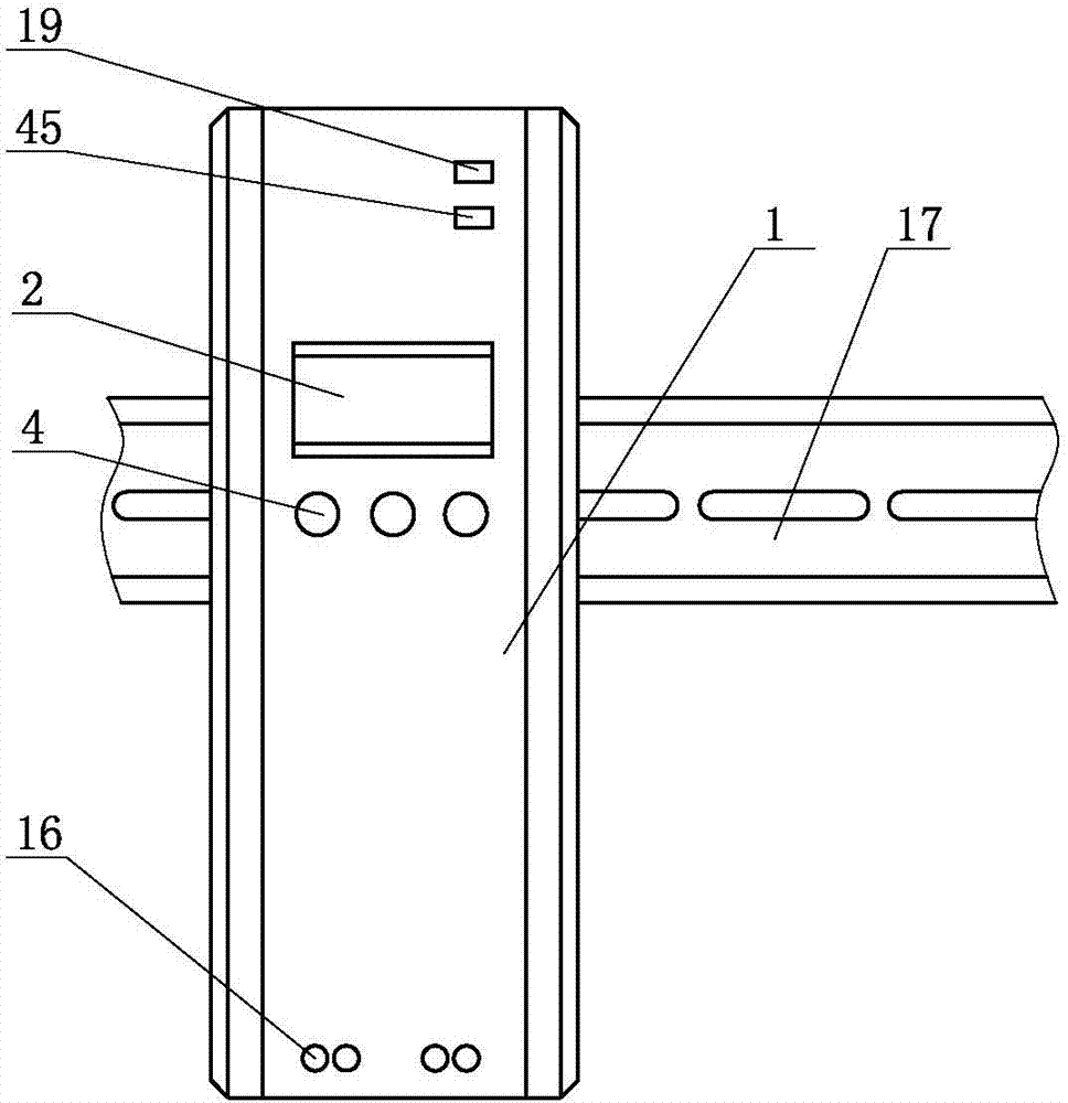
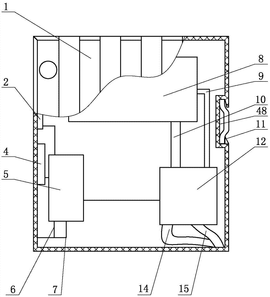
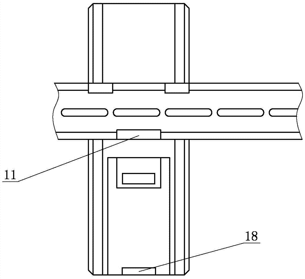
[0017] The new terminal box dehumidification heater includes a chassis 1, in which a processor 5, a condensation chamber 8, and a dehumidifier 12 are respectively installed, and a display screen 2, function buttons 4, wiring terminals 16, and power indicator lights are respectively installed on the chassis 1 19. The communication indicator light 45 and the drain pipe port 18, the dehumidifier 12 is connected with the processor 5 through the connection line 3, the dehumidifier 12 is connected with the condensation chamber 8 through the air pipe 9 and the water pipe 10, and the dehumidifier 12 is connected with the dehumidifier Air pipe 15 and drain pipe 14, drain pipe 14 is connected with drain pipe mouth 18, processor 5 is connected with display screen 2, function key 4 and connection terminal 16 respectively. When in use, after the terminal is connected to the power line and signal line, set the upper limit and lower limit of the automatic dehumidification through the function...


PUM


Abstract

A novel terminal case dehumidifying heater comprises a case. The case is internally provided with a processor, a condensation chamber and a dehumidifier; a display screen, function keys, wiring terminals, a power indication lamp, a communication indication lamp and a drain pipe port are arranged on the case; the dehumidifier is connected with the processor through a connection wire; the dehumidifier is connected with the condensation chamber through an air pipe and a water pipe; a suction pipe and a drain pipe are connected onto the dehumidifier; the drain pipe is connected with the drain pipe port; and the processor is respectively connected with the display screen, the function keys and the wiring terminals. Due to a communication interface, data can be remotely transmitted and software is connected for realizing remote monitoring, and the case condensation phenomenon can be finally solved. High-efficiency and thorough dehumidifying can be realized, elements in the case are not damaged at all during the dehumidifying process, the data can be remotely transmitted and software is connected for realizing remote monitoring, and the case condensation phenomenon can be finally solved.

Description

technical field [0001] The invention relates to the technical field of power transformation equipment operation and maintenance, in particular to a novel terminal box dehumidification heater. Background technique [0002] The internal space of the currently used terminal box is very compact, and various actuators are arranged densely. During the operation of the equipment, severe condensation often occurs, and even some devices may experience slight corrosion. Condensation is more serious in the rainy season or when the temperature difference between morning and evening is large in spring and autumn, and it may even cause icing when the temperature is low in winter. [0003] Moisture and condensation in the cabinet will cause the following problems: [0004] 1. The electrical equipment is rusted, causing the rotating parts to fail when performing work; [0005] 2. After the electrical equipment is severely damp, it is easy to cause electrical breakdown or insulation drop, ...

Claims


Application Information

Patent Timeline
IPC IPC(8): G05D27/02
CPCG05D27/02
Inventor 苏雷尹国慧王磊汪际洲于强李守金杨淑增李厚义孙国先张志强唐超袁立国袁峰赵伟健
Owner STATE GRID SHANDONG ELECTRIC POWER
Features
  • Generate Ideas
  • Intellectual Property
  • Life Sciences
  • Materials
  • Tech Scout
  • Unparalleled Data Quality
  • Higher Quality Content
  • 60% Fewer Hallucinations
Learn More