LED constant-current drive circuit

A technology of constant current drive and circuit, which is applied in the field of LED constant current drive circuit, can solve the problems of high cost and complex circuit structure, and achieve the effect of low cost, less circuit electronic components, and low total harmonic distortion

Inactive Publication Date: 2017-08-25
湖州灵感电子科技有限公司
View PDF6 Cites 0 Cited by
  • Summary
  • Abstract
  • Description
  • Claims
  • Application Information

AI Technical Summary

Problems solved by technology

Existing LED constant current drive power supplies are generally equipped with special power factor calibration and dynamic voltage control circuits to achieve high power factor constant current source drivers. The circuit usually uses more electronic components, resulting in a more complex circuit structure and lower cost. high

Method used


Image

  • LED constant-current drive circuit

Examples


Embodiment Construction

[0017] Embodiments of the present invention will be described in further detail below in conjunction with the accompanying drawings.

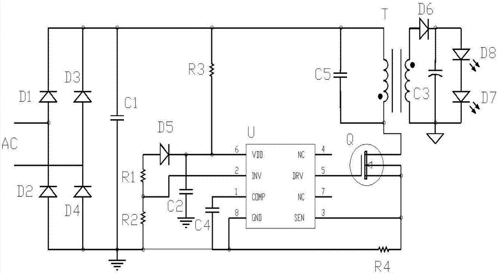
[0018] Such as figure 1 As shown, an LED constant current drive circuit, diodes D1~D4 and capacitor C1 are connected in parallel to form a rectifier filter module, resistors R1~R3 ​​are connected in series with diode D5 and then parallel capacitor C2 is used to form a feedback sampling circuit, resistor R4, diode D6, capacitor C3 and C5, reverse transformer T and MOS tube Q form a flyback converter, U is a constant current drive control chip integrated with a PFC circuit, 1-pin COMP loop compensation, 2-pin INV feedback signal sampling, 3-pin SEN current sampling, 4 Pin and pin 7 NC are suspended, pin 5 is DRV external power MOS transistor gate drive pin, pin 6 is VDD chip power supply pin, pin 8 is grounded.

[0019] The AC mains input passes through the bridge rectifier circuit composed of diodes D1~D4 to output a half sine wave DC voltage s...


PUM


Abstract

The invention relates to an LED constant-current drive circuit. The LED constant-current drive circuit comprises a rectification filter module, a primary side flyback power conversion module and a constant-current driving module, wherein alternating current mains supply input is connected with the rectification filter module and is in output connection with an LED load through the primary side flyback power conversion module and the constant-current driving module. Higher power factors and low total harmonic distortion can be realized, optocoupler devices of primary side regulation and special dynamic voltage control circuits are not required, and high-PFC and high-accuracy LED constant current output is guaranteed. The LED constant-current drive circuit requires fewer circuit electronic elements and is simpler in structure and lower in cost.

Description

[0001] Technical field: [0002] The invention relates to an electronic circuit, in particular to an LED constant current drive circuit. [0003] Background technique: [0004] Due to the special forward volt-ampere characteristics of the LED, it needs a constant current power supply. Existing LED constant current drive power supplies are generally equipped with special power factor calibration and dynamic voltage control circuits to achieve high power factor constant current source drivers. The circuit usually uses more electronic components, resulting in a more complex circuit structure and lower cost. On the high side. [0005] Invention content: [0006] (1) Technical problems to be solved [0007] In view of the above problems, the present invention provides an LED constant current drive circuit, which does not require an optocoupler device for primary side feedback and a special dynamic voltage control circuit to ensure high PFC and high precision LED constant current ...

Claims


Application Information

Patent Timeline
Patent Type & Authority Applications(China)
IPC IPC(8): H05B33/08H05B44/00
CPCH05B45/37
Inventor 施卫杰
Owner 湖州灵感电子科技有限公司
Why Eureka
Try Eureka