Eureka AIR delivers breakthrough ideas for toughest innovation challenges, trusted by R&D personnel around the world.

Steel pipe fixing device

A fixing device and technology of steel pipes, applied in the field of steel pipes, can solve problems such as difficulty in fixing and positioning steel pipes, low efficiency of cutting and segmented processing of steel pipes, and inability to meet the fixing requirements of steel pipes with various diameters, etc., so as to achieve convenient cutting and segmented processing, Fixed and stable effect

Active Publication Date: 2017-08-29
NANTONG YONGDA PIPE IND
View PDF7 Cites 2 Cited by
  • Summary
  • Abstract
  • Description
  • Claims
  • Application Information

AI Technical Summary

Problems solved by technology

[0002] Nowadays, steel pipes are widely used. It is not only used to transport liquids, but also used to manufacture building steel structure frames. Due to the different places where steel pipes are used and the lengths they need to use, steel pipes need to be cut and segmented before use. To meet the needs of the steel pipe, but the steel pipe is basically cylindrical, and there are steel pipes of different diameters, which makes the fixing and positioning of the steel pipes more difficult. The general fixing device can only fix the steel pipes of the same diameter, and it is difficult to fix other steel pipes of different diameters. Steel pipes, which lead to the increase of the fixed cost of steel pipes, making the cutting and segmentation processing efficiency of steel pipes low. Therefore, the general fixing device cannot meet the fixing needs of various existing steel pipes with different diameters.

Method used


Image

  • Steel pipe fixing device
  • Steel pipe fixing device
  • Steel pipe fixing device

Examples


Embodiment Construction

[0020] The preferred embodiments of the present invention will be described in detail below in conjunction with the accompanying drawings, so that the advantages and features of the present invention can be more easily understood by those skilled in the art, so as to define the protection scope of the present invention more clearly.

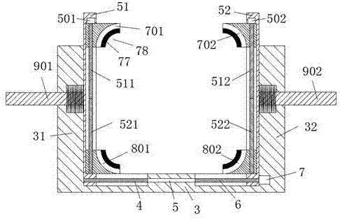
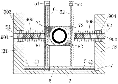
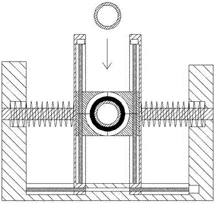
[0021] refer to Figure 1-4 The steel pipe fixing device shown includes a base 3, and the left and right convex columns 31 and 32 are symmetrically arranged on the left and right ends of the top of the base 3, and the left convex column 31 and the right convex column 32 are respectively symmetrically arranged with The left guide hole 91 and the right guide hole 92, the inner ends of the left boss 31 and the right boss 32 are respectively symmetrically provided with a left counterbore 903 and a right counterbore communicating with the left guide hole 91 and the right guide hole 92 904, the top of the base 3 is located at the inner end of the left ...


PUM


Abstract

The invention discloses a steel pipe fixing device. The steel pipe fixing device comprises a base; a left convex column and a right convex column are symmetrically arranged at the left and right ends of the top of the base; a left guide hole and a right guide hole are symmetrically formed in the left convex column and the right convex column; a left counter bore communicating with the left guide hole and a right counter bore communicating with the right guide hole are symmetrically formed in the inner side ends of the left convex column and the right convex column; a first left chute and a first right chute are symmetrically formed in the parts, positioned at the inner side ends of the left convex column and the right convex column, of the top of the base; a left slide frame and a right slide frame capable of sliding left and right are symmetrically arranged in the first left chute and the first right chute; and a second left chute and a second right chute are symmetrically formed in the inner side ends of the left slide frame and the right slide frame. The device is simple in structure and low in production cost, can clamp and fix steel pipes of different diameters, is convenient and fast in taking-down, clamping and fixation of the steel pipes, improves the machining efficiency of subsequent cutting segmentation of the steel pipes, is simple and convenient to operate, is safe, reliable and reasonable in overall structure operation, and is suitable for popularization and application.

Description

technical field [0001] The invention relates to the technical field of steel pipes, in particular to a steel pipe fixing device. Background technique [0002] Nowadays, steel pipes are widely used. It is not only used to transport liquids, but also used to manufacture building steel structure frames. Due to the different places where steel pipes are used and the lengths they need to use, steel pipes need to be cut and segmented before use. To meet the needs of the steel pipe, but the steel pipe is basically cylindrical, and there are steel pipes of different diameters, which makes the fixing and positioning of the steel pipes more difficult. The general fixing device can only fix the steel pipes of the same diameter, and it is difficult to fix other steel pipes of different diameters. Steel pipes, which lead to the increase of steel pipe fixing costs, making the cutting and segmentation processing efficiency of steel pipes low. Therefore, general fixing devices cannot meet t...

Claims


Application Information

Patent Timeline
Patent Type & Authority Applications(China)
IPC IPC(8): B23D21/00B23D33/04
CPCB23D21/00B23D33/04
Inventor 姚莉萍
Owner NANTONG YONGDA PIPE IND
Why Eureka
Eureka Blog
Learn More