Vibrating piezoelectric spray head system

A technology of vibration pressure and vibrating plate, applied in the field of 3D printing, can solve the problems of scrapping, high fluid viscosity, easy plugging, etc., and achieve the effect of simple replacement, easy control of flow rate and improved precision

Pending Publication Date: 2017-08-29
GUIZHOU UNIV
View PDF6 Cites 4 Cited by
  • Summary
  • Abstract
  • Description
  • Claims
  • Application Information

AI Technical Summary

Problems solved by technology

[0004] The technical problem to be solved by the present invention is: to provide a vibrating piezoelectric nozzle system, which has the advantages of ingenious design, simple structure, and convenient replacement, and can solve the problem that existing printer nozzles are easily blocked due to high fluid viscosity, and are seriously scrapped.

Method used


Image

  • Vibrating piezoelectric spray head system
  • Vibrating piezoelectric spray head system
  • Vibrating piezoelectric spray head system

Examples


Embodiment Construction

[0023] Below in conjunction with accompanying drawing and specific embodiment the invention is further introduced:

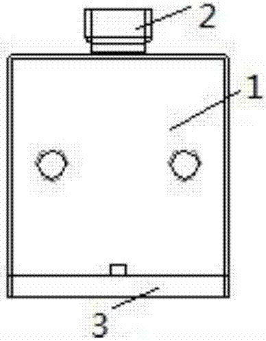
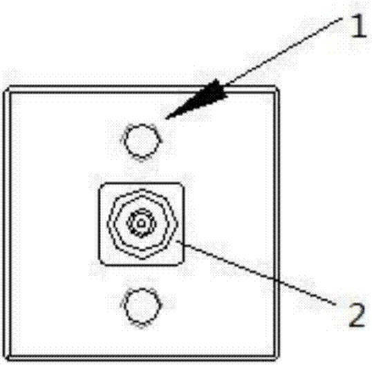
[0024] refer to Figure 1 to Figure 7 , a vibrating piezoelectric nozzle system of the present invention, comprising a liquid storage chamber 1, a liquid supply joint 2 and a liquid outlet, the liquid supply joint 2 is arranged above the liquid storage chamber 1, and the liquid outlet is arranged on the liquid storage chamber 1 At the bottom, a groove for installing a piezoelectric ceramic vibration mechanism 4 is provided at the bottom of the liquid storage chamber 1, and a piezoelectric ceramic vibration mechanism 4 for vibrating to eject fluid is installed in the groove.

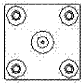
[0025] The piezoelectric ceramic vibrating mechanism 4 comprises a ring-shaped piezoelectric ceramic vibrating piece 42 and a metal piece 41 bonded together, and the ring-shaped piezoelectric ceramic vibrating piece 42 and the metal piece 41 are provided with a protrusion communicating with...


PUM


Abstract

The invention discloses a vibrating piezoelectric spray head system. The vibrating piezoelectric spray head system comprises a liquid storage cavity. A liquid supply connector is arranged above the liquid storage cavity. A liquid outlet is formed in the bottom of the liquid storage cavity. A piezoelectric ceramic vibrating mechanism used for vibrating so as to spray fluid is arranged at the bottom of the liquid storage cavity. The piezoelectric ceramic vibrating mechanism comprises an annular piezoelectric ceramic vibrating piece and a metal piece, wherein the annular piezoelectric ceramic vibrating piece and the metal piece are bonded together, convex conical holes communicating with the liquid outlet are formed in the annular piezoelectric ceramic vibrating piece and the metal piece, and a vibrating signal of the piezoelectric ceramic vibrating mechanism is guided in through an electrode on one side of the annular piezoelectric ceramic vibrating piece and an electrode on one side of the metal piece. Compared with the prior art, the vibrating piezoelectric spray head system is large in vibrating amplitude, and the problems that an existing printer spray head is prone to being blocked due to the fact that the fluid viscosity is large and is scrapped when severely blocked can be effectively solved.

Description

technical field [0001] The invention relates to a vibrating piezoelectric nozzle system, which belongs to the technical field of 3D printing. Background technique [0002] Additive manufacturing (3D printing) technology has spawned a large number of new production methods and changed the manufacturing process of traditional products. In particular, the traditional design, mold opening, pouring and other processes are no longer satisfactory to people's expectations for products. The traditional manufacturing process has high energy consumption, long cycle time, serious pollution and other disadvantages. Moreover, traditional manufacturing methods for complex devices cannot be satisfied. Coupled with the improvement of people's living standards, personalized customized products will also be the general trend. [0003] 3D printing abroad is in full swing. From the biological fields such as tissue culture to the living fields such as food printing and clothing printing, and th...

Claims


Application Information

Patent Timeline
Patent Type & Authority Applications(China)
IPC IPC(8): B29C64/112B29C64/209B33Y30/00
CPCB33Y30/00
Inventor 李渊杨晓宏
Owner GUIZHOU UNIV
Why Eureka
Try Eureka