
Fan blade anti-icing and de-icing system based on air heating

A technology for fan blades and air heating, which is applied to wind turbines, wind turbines, motors, etc. in the same direction as the wind, and can solve problems such as generator set damage, off-grid shutdown, and blade overload loads.

Active Publication Date: 2019-03-29
HUNAN TUOTIAN ENERGY SAVING CONTROL TECH
View PDF6 Cites 1 Cited by
  • Summary
  • Abstract
  • Description
  • Claims
  • Application Information

AI Technical Summary

Problems solved by technology

Frozen blades will lead to blade overload and unbalanced load, resulting in reduced fan operating efficiency
Continuing to operate the blade in the frozen state will also change the original airfoil of the blade, resulting in the deterioration of the aerodynamic performance of the blade, resulting in a sharp decline in the wind energy capture capacity. When the ice accumulation is serious, the load will increase and the vibration will increase. Generator sets produce very large hazards
When the icing is severe, the unit must be disconnected from the grid to stop, and the utilization rate of the unit will drop, resulting in loss of power generation
In addition, after the blade freezes, as the temperature rises, the ice cubes will fall off, and the distance that the falling ice cubes will be thrown out can reach 1.5 times the height of the blade tip, which will cause a greater safety hazard to the crew and on-site personnel.
[0003] However, the existing air-heated fan blade deicing system has technical problems such as slow deicing speed, high energy consumption, high cost, uneven heating, and difficulty in reaching the blade tip.

Method used


Image

  • Fan blade anti-icing and de-icing system based on air heating
  • Fan blade anti-icing and de-icing system based on air heating
  • Fan blade anti-icing and de-icing system based on air heating

Examples


Embodiment Construction

[0028] The specific embodiments of the present invention will be further described below in conjunction with the accompanying drawings. It should be noted here that the descriptions of these embodiments are used to help understand the present invention, but are not intended to limit the present invention. In addition, the technical features involved in the various embodiments of the present invention described below may be combined with each other as long as they do not constitute a conflict with each other.

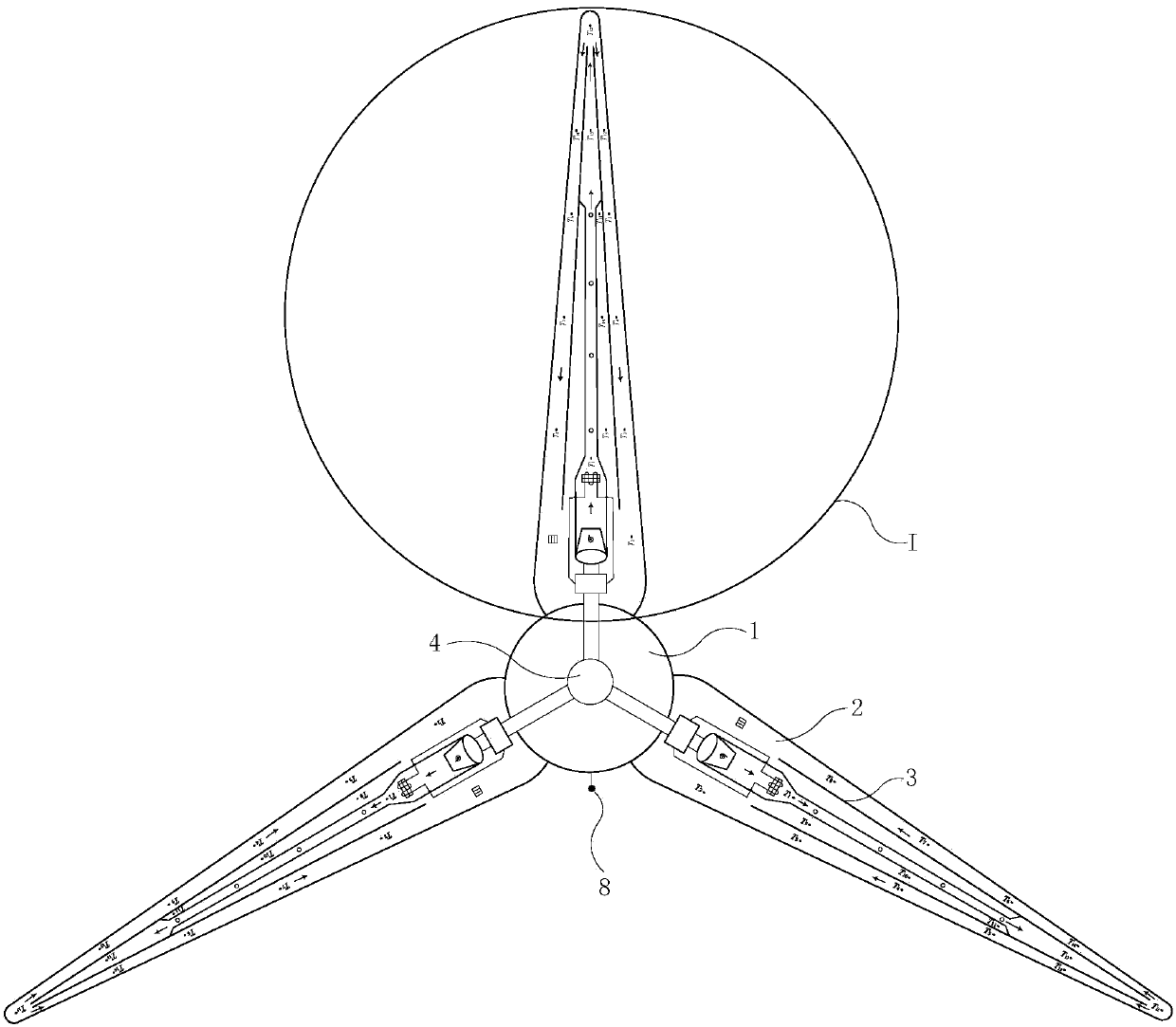
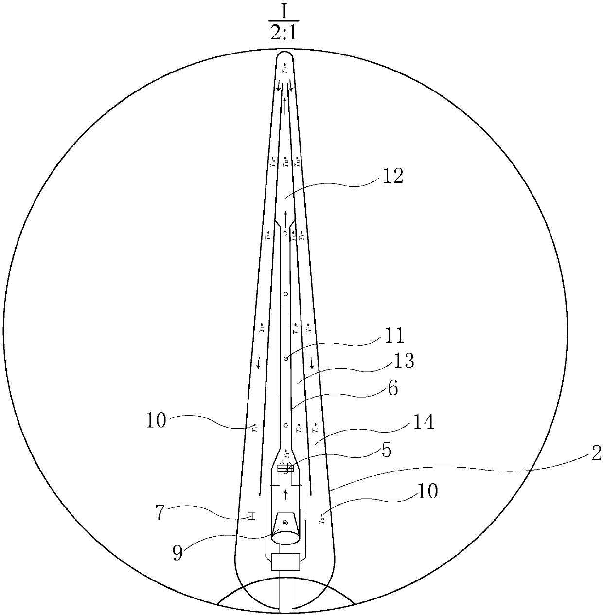
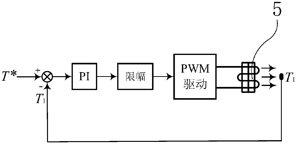
[0029] as attached figure 1 And attached figure 2 As shown, the fan blade anti-icing and de-icing system based on air heating includes fan hub 1 , fan blade 2 , and blade inner support frame baffle 3 . The fan blade 2 is connected with the fan hub 1 , and the blade inner support frame baffle 3 is connected with the fan blade 2 . It also includes a controller 4, a heater 5, a ventilation pipe 6, an ice detector 7, a temperature and humidity sensor 8, an electric turbo...


PUM


Abstract

The invention discloses a fan blade anti-icing and deicing system based on air heating. The system comprises a controller, heaters, vent pipes, ice detectors, a temperature and humidity sensor, electric turbochargers and a plurality of blade internal temperature sensors; the temperature and humidity sensor is connected to a fan hub; the ice detectors are connected to fan blades; each vent pipe is arranged on the inner sides of two blade internal supporting framework baffles; the heaters are arranged at the front ends of the vent pipes; the electric turbochargers are arranged at air inlets at the front ends of the heaters; the multiple blade internal temperature sensors are uniformly arranged on the fan blades; and the controller is electrically connected to the temperature and humidity sensor, the ice detectors, the heaters, the electric turbochargers and the blade internal temperature sensors. According to the fan blade anti-icing and deicing system, closed-loop linear control is carried out on the power of the heaters and the turbine rotating speed of the electric turbochargers, and therefore the energy consumption of the system can be reduced, the use cost can be lower, heating can be more uniform, anti-icing and deicing can be effectively realized, and the service life and the performance of the fan blades can be improved.

Description

technical field [0001] The invention relates to the field of wind power generation, in particular to an anti-icing and de-icing system for fan blades based on air heating. Background technique [0002] In places with low temperature, high humidity and high altitude, fan blades are prone to freezing. Frozen blades will lead to blade overload and unbalanced load, resulting in reduced fan operating efficiency. Continuing to operate the blade under icing conditions will change the original airfoil of the blade, resulting in deterioration of the aerodynamic performance of the blade, resulting in a sharp drop in wind energy capture capacity. When the ice accumulation is severe, the load increases and the vibration intensifies. Generator sets create a very large hazard. When the icing is severe, the unit must be disconnected from the grid to stop, and the utilization rate of the unit will drop, resulting in a loss of power generation. In addition, after the blade freezes, as the...

Claims


Application Information

Patent Timeline
Patent Type & Authority Patents(China)
IPC IPC(8): F03D80/40F03D80/60F03D17/00F03D1/06
CPCF03D1/0675F03D17/00F03D80/40F03D80/60Y02E10/72
Inventor 范必双孟庆辉刘志龙
Owner HUNAN TUOTIAN ENERGY SAVING CONTROL TECH
Learn More