Vehicle lamp heater and vehicle lamp

A technology of heaters and heating resistors, which is applied in the direction of headlights, lighting and heating equipment, cooling/heating devices of lighting devices, etc., can solve problems such as long time, achieve effective heat transfer and improve heat dissipation

Pending Publication Date: 2017-08-29
BORGWARNER BERU SYST
View PDF5 Cites 0 Cited by
  • Summary
  • Abstract
  • Description
  • Claims
  • Application Information

AI Technical Summary

Problems solved by technology

However, it still takes a considerable amount of time to de-ice the tr

Method used


Image

  • Vehicle lamp heater and vehicle lamp
  • Vehicle lamp heater and vehicle lamp
  • Vehicle lamp heater and vehicle lamp

Examples


Embodiment Construction

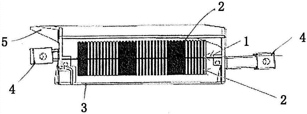
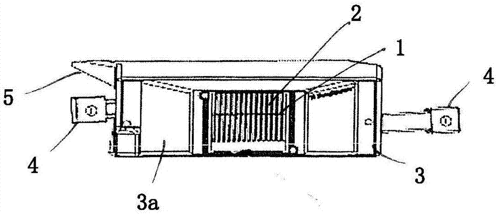
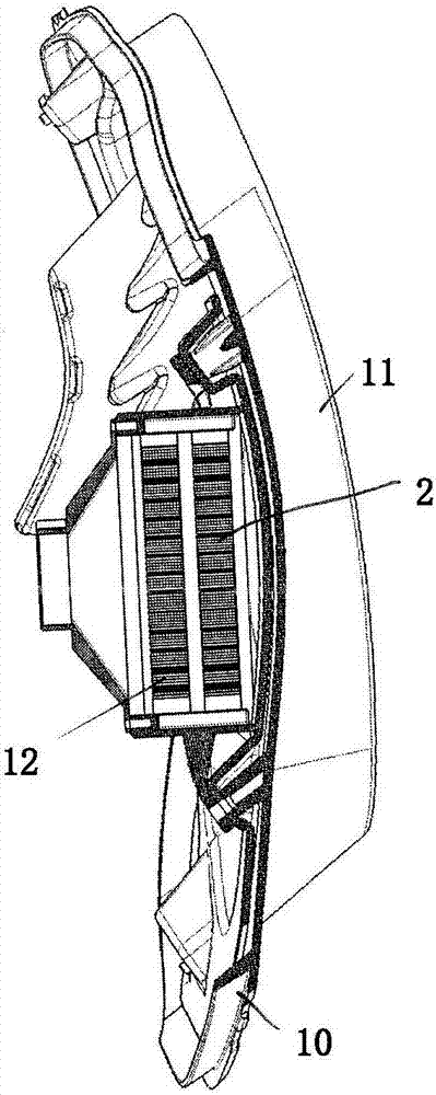
[0019] figure 1 The car lamp heater shown in includes: a polymer PTC heating resistor 1 , two metal cooling bodies 2 , and a holder 3 for holding the polymer PTC heating resistor 1 and the cooling bodies 2 . The bracket 3 is made of plastic, for example PC, PA66, PBT or other thermoplastic, and comprises an attachment element 4 for fixing the bracket to the housing of the vehicle light. The attachment elements may eg comprise eyelets or flanges.

[0020] Polymer PTC heating resistors have metal coatings on opposite sides. Terminals for connection to a power source, such as the vehicle electrical system, may be attached to the metal coating, for example by soldering or welding.

[0021] A polymer PTC heating resistor can be a layer arranged between two metal plates. The polymer PTC heating resistor is electrically insulated from the cooling body 2 , for example by an electrically insulating adhesive or glue covering the metallic coating of the PTC heating resistor. The heat...


PUM


Abstract

This disclosure refers to a vehicle lamp heater, comprising a PTC heating resistor, a metallic cooling body fixed to the PTC heating resistor, and a holder holding the PTC heating resistor and the metallic cooling body. Also disclosed are a vehicle lamp comprising a plastic housing with a transparent cover and such a vehicle lamp heater.

Description

technical field [0001] The invention relates to a car lamp heater and a car lamp including the car lamp heater. Background technique [0002] Modern car lights increasingly contain light-emitting diodes (LEDs) instead of halogen bulbs. LEDs provide an advantageous reduction in power consumption, but do not generate enough heat to prevent condensation from accumulating on the inside of the lamp's transparent cover. [0003] US 7 262 388 B2 discloses a vehicle lamp comprising a PTC heating resistor mounted on the lamp housing. The PTC heating resistors are provided as a series of conductive tracks arranged on the inner or outer surface of the lamp housing adjacent to the transparent cover. However, at freezing temperatures, eg -20°C, it still takes a considerable amount of time to de-ice the transparent cover of the headlamp. Contents of the invention [0004] It is therefore an object of the present invention to show how to quickly de-ice vehicle lights, in particular ve...

Claims


Application Information

Patent Timeline
IPC IPC(8): F21S8/10F21V29/90F21V29/67F21V29/70F21V29/89F21W101/02F21W101/10F21Y115/10
CPCF21S45/60F21S45/43F21S41/141F21S45/47F21W2102/00F21W2107/10B60Q1/0017B60Q1/0005
Inventor K·奥沙利文C·麦卡锡D·奥卡罗
Owner BORGWARNER BERU SYST
Why Eureka
Try Eureka