
Test apparatus, system and method for obtaining vibration fatigue limit of welded pipe

A test device and vibration fatigue technology, which is applied in the field of test devices for obtaining the vibration fatigue limit of welding pipelines, can solve problems such as pipeline fatigue cracks, threats to the safety of aeroengines, pipeline oil leakage and air leakage, etc., to achieve accurate acquisition, fatigue The test method is correct and feasible, and the system is stable and reliable

Inactive Publication Date: 2017-08-29
AECC HUNAN AVIATION POWERPLANT RES INST
View PDF2 Cites 13 Cited by
  • Summary
  • Abstract
  • Description
  • Claims
  • Application Information

AI Technical Summary

Problems solved by technology

At the same time, the pipe joint and the pipe body are connected by welding, and there is welding residual stress
[0003] Under the action of various alternating loads, the pipeline is prone to fatigue cracks, causing oil leakage and air leakage in the pipeline, which seriously threatens the safety of aero-engines

Method used


Image

  • Test apparatus, system and method for obtaining vibration fatigue limit of welded pipe
  • Test apparatus, system and method for obtaining vibration fatigue limit of welded pipe
  • Test apparatus, system and method for obtaining vibration fatigue limit of welded pipe

Examples


Embodiment Construction

[0048] The technical solutions of the present invention will be further described below according to specific embodiments. The protection scope of the present invention is not limited to the following examples, which are listed for illustrative purposes only and do not limit the present invention in any way.

[0049] Fatigue life is the number of stress cycles experienced by a structure before fatigue cracks develop at a specified stress level. In general, the fatigue life of a component is determined by its fatigue test. Under linear elastic conditions, it is usually determined by the stress-fatigue curve (S-N curve) of the material or part. The stress fatigue curve is based on the stress amplitude S and the corresponding failure cycle number N L The curve made between the measured data. However, in general, the S-N curve is obtained through fatigue tests, which is long-term and expensive. From the perspective of engineering applications, an empirical formula for the shape...


PUM


Abstract

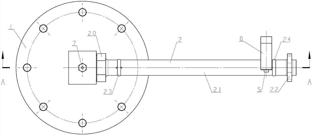
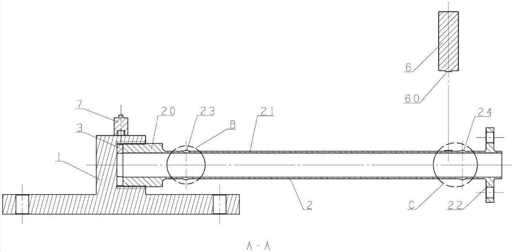
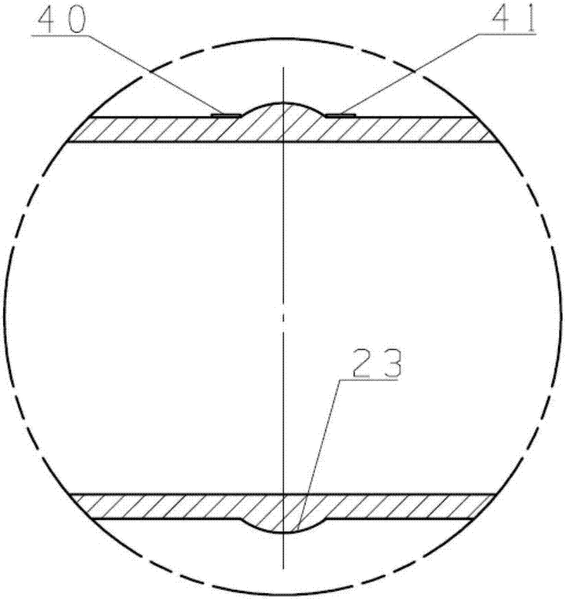
The invention provides a test apparatus, system and method for obtaining a vibration fatigue limit of a welded pipe. The test apparatus comprises a mounting seat having a receiving part; a pipe having a pipe joint, a pipe body and an installation section, the pipe body being located between the pipe joint and the installation section; a plurality of strain gauges adhered to the pipe body and used for measuring the vibration stress of the pipe and converting it into a dynamic strain signal; a displacement measuring sensor disposed above the pipe body and keeping a distance from the pipe body for measuring the displacement of the pipe during vibration and converting it into a vibration displacement signal; a vibration acceleration sensor which is fixedly arranged above the housing portion for acquiring the vibration acceleration signal of the pipe and converting the vibration acceleration signal into a dynamic analog voltage signal. The pipe joint is fixed in the housing portion. The test apparatus of the invention is reasonable in design and stable and reliable in system operation, and the fatigue test method is correct and feasible.

Description

technical field [0001] The invention relates to the field of engine detection, in particular to a test device, system and method for obtaining the vibration fatigue limit of welding pipelines. Background technique [0002] There are many aero-engine pipelines, including fuel pipelines, lubricating oil pipelines and air pipelines, etc., which are complex in shape and are generally welded by pipe joints and pipe bodies. When the aero-engine is working, the pipeline is subjected to various mechanical vibrations, aerodynamic excitation, etc., and not only bears steady-state stress, but also bears vibration stress. At the same time, the pipe joint and the pipe body are connected by welding, and there is welding residual stress. [0003] Under the action of various alternating loads, the pipeline is prone to fatigue cracks, resulting in oil and air leakage from the pipeline, which seriously threatens the safety of the aero-engine. Fatigue cracks first occur in the places where t...

Claims


Application Information

Patent Timeline
IPC IPC(8): G01M7/02
CPCG01M7/025
Inventor 边杰张春月刘超
Owner AECC HUNAN AVIATION POWERPLANT RES INST
Learn More