Oil-immersed current transformer live-wire sampling device and sampling method based thereon

A technology of current transformers and sampling devices, which is applied in the direction of sampling devices, inductors, sampling, etc., can solve the problems of contaminated oil sample analysis data, inaccuracy, etc., and achieve the goals of improving accuracy, reliable sampling, and preventing oil leakage at the valve port Effect

Inactive Publication Date: 2017-08-29
NANCHONG POWER SUPPLY COMPANY STATE GRID SICHUANELECTRIC POWER
View PDF7 Cites 0 Cited by
  • Summary
  • Abstract
  • Description
  • Claims
  • Application Information

AI Technical Summary

Problems solved by technology

[0004] The technical problem to be solved by the present invention is to improve the accuracy of oil sample analysis data, the purpose is to provide an oil-immersed curre

Method used


Image

  • Oil-immersed current transformer live-wire sampling device and sampling method based thereon

Examples


Embodiment 1

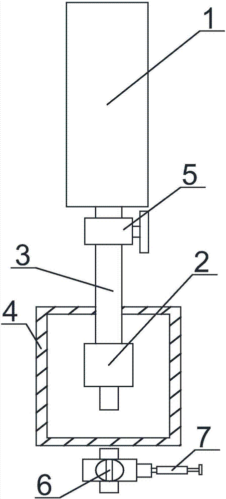
[0032] Such as figure 1 As shown, the oil-immersed current transformer live sampling device of the present invention includes a sampling valve 2 communicated with the current transformer 1 oil tank, and the current transformer 1 oil tank is connected with the sampling valve 2 through the connecting pipe 3, and the outside of the sampling valve 2 Covered with a protective cover 4, the sampling valve 2 is completely inside the protective cover 4. The connecting pipe 3 is a stainless steel pipe with an inner diameter of 4 mm and an outer diameter of 6 mm.

[0033] In the present invention, a connecting pipe is added to the sampling port of the current transformer oil tank, and the connecting pipe is downwardly connected to the sampling valve, which reduces the position of sampling and thereby reduces the risk of sampling, and realizes safe and reliable sampling; the sampling valve is installed on the protective cover Inside, on the one hand, the protective cover plays the role o...

Embodiment 2

[0035] Based on embodiment 1, the sampling valve 2 adopts a needle sampling valve, the front end of the sampling valve 2 is a sampling nozzle, and the rear end of the sampling valve 2 is a cylindrical sealing core, and the cylindrical sealing core is connected to the connecting pipe 3 . The inner hole diameter of the sampling nozzle of the sampling valve 2 is 5.0 mm-8.0 mm, and the inner hole diameter of the cylindrical sealing core of the sampling valve 2 is 1 cm. The structure of the sampling valve in the invention can ensure the tightness of oil taking, and make the oil sample flow out continuously and evenly, and prevent the waste of oil. The present invention optimizes the size of the sampling valve, the larger the diameter of the sampling nozzle, the poorer the sealing performance, and the larger the diameter of the sampling nozzle, the more oil samples it will flow out at one time; but the smaller the diameter of the sampling nozzle, the slower its sampling speed, low ...

Embodiment 3

[0037] Based on the above embodiments, the connection between the oil tank of the current transformer 1 and the connecting pipe 3, and the connection between the connecting pipe 3 and the sampling valve 2 are all welded connections. Welded connection, firm and reliable, effectively prevent oil leakage.


PUM

PropertyMeasurementUnit
Bore diameteraaaaaaaaaa
The inside diameter ofaaaaaaaaaa

Abstract

The invention discloses an oil-immersed current transformer live-wire sampling device and a sampling method based thereon; the oil-immersed current transformer live-wire sampling device comprises a sampling valve communicated with a current transformer oil tank, the current transformer oil tan is connected with the sampling valve through a connection pipe, the sampling valve is covered with a protective hood, and the sampling valve is completely positioned within the protective hood. The sampling position of the sampling valve is lowered through the connection pipe, and safe and reliable sampling is achieved; through the protective hood, it is effectively avoided that mistaken touch for the sampling valve leads to contamination of the sampling valve or that oil leaks from a port of the sampling valve, and sampling analysis data is more accurate.

Description

technical field [0001] The invention relates to a sampling device and method for a current transformer, in particular to a live sampling device and a sampling method for an oil-immersed current transformer. Background technique [0002] Current transformers are widely used in relay protection, system monitoring, power system analysis and other fields. In order to ensure the safe operation of voltage and current transformers and power systems, it is necessary to collect oil samples for analysis from time to time. [0003] The existing current transformer is provided with an oil sampling port, and the oil sampling port is provided with an inner valve and an outer valve. When sampling, the outer valve and the inner valve must be opened in order to start sampling. After sampling, the inner valve and the inner valve must be closed in turn. Outer valve. There are certain risks in live sampling of existing current transformers. First, the sampling position is relatively high (espe...

Claims


Application Information

Patent Timeline
IPC IPC(8): G01N1/10H01F38/30H01F27/00
CPCG01N1/10G01N2001/1031H01F27/00H01F38/30
Inventor 刘晨晨冯胜杨文新张大猛杨皓邓镓卓赵冲罗进张升
Owner NANCHONG POWER SUPPLY COMPANY STATE GRID SICHUANELECTRIC POWER
Why Eureka
Try Eureka