A light guide plate and a backlight module using the light guide plate

A technology of backlight module and light guide plate, which is applied in the direction of light guide, optics, optical components, etc., can solve the problem that it is difficult to control the crosstalk of optical paths in different partitions, and achieve the effects of reducing crosstalk of optical paths, improving convergence characteristics, and reducing crosstalk of optical paths

Active Publication Date: 2019-06-11
WUHAN CHINA STAR OPTOELECTRONICS TECH CO LTD
View PDF11 Cites 0 Cited by
  • Summary
  • Abstract
  • Description
  • Claims
  • Application Information

AI Technical Summary

Problems solved by technology

However, the small-sized 1D Local Dimming technology is often difficult to control the crosstalk of optical paths in different partitions

Method used


Image

  • A light guide plate and a backlight module using the light guide plate
  • A light guide plate and a backlight module using the light guide plate
  • A light guide plate and a backlight module using the light guide plate

Examples


Embodiment Construction

[0019] The following will clearly and completely describe the technical solutions in the embodiments of the present invention with reference to the drawings in the embodiments of the present invention.

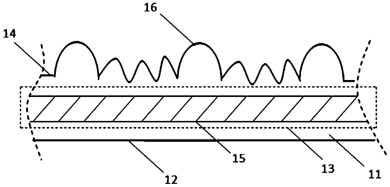
[0020] see figure 1 , figure 1 It is an embodiment of the light guide plate 11 of the present invention, including a light incident surface 12, a transmission layer 13, and a light exit surface 14; perpendicular to the light-emitting surface 14; the light-emitting surface 14 is provided with a periodic microstructure 16;

[0021] The microstructures 16 are divided according to bright or dark areas on the surface of the light guide plate 11, each of the bright or dark areas corresponds to a period of the microstructures 16;

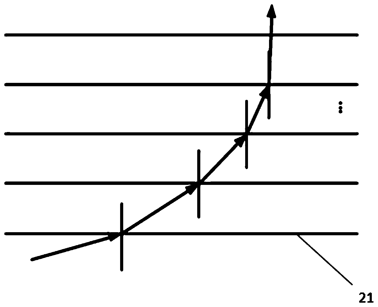
[0022] The optical waveguide layer 15 includes a plurality of transparent medium layers 21, please refer to figure 2 ; The refractive index of the transparent medium layer 21 increases in the direction of propagation of the light; the material of the t...


PUM


Abstract

A light guide plate and a backlight module, the light guide plate (11) comprising: a light entering surface (12), a transmission layer (13) and a light exiting surface (14); the transmission layer (13) is provided with a light wave conducting layer (15) such that at least a portion of the propagation direction of a light ray which enters from the light entering surface (12) is perpendicular to the light exiting surface (14); the light exiting surface (14) is provided with a periodic microstructure (16). The backlight module comprises the light guide plate (11). The light wave conducting layer (15) helps to enhance the light collecting performance of the light guide plate (11), reduce optical path crosstalk between each partition, and achieve an ultra-thin and small crosstalk 1D display partitioning effect.

Description

technical field [0001] The invention relates to the field of backlight modules of liquid crystal displays, in particular to a light guide plate and a backlight module using the light guide plate. Background technique [0002] High-Dynamic Light Rendering (High-Dynamic Range, HDR) images can provide more dynamic range and image details than ordinary images. According to LDR (Low-Dynamic Range) images with different exposure times, each exposure The LDR image with the best details corresponding to the time is used to synthesize the final HDR image, which can better reflect the visual effect in the real environment. [0003] The local dimming technology plays an important role in the realization of sensors required to synthesize high dynamic range ("HDR") images on mobile terminals. Local Dimming technology is local backlight adjustment technology, which is adjusted according to the light and shade of the image: the brightness of the highlighted part of the display screen imag...

Claims


Application Information

Patent Timeline
Patent Type & Authority Patents(China)
IPC IPC(8): G02B6/00G02F1/13357
CPCG02B6/0011G02B6/0038G02F1/133615
Inventor 程艳
Owner WUHAN CHINA STAR OPTOELECTRONICS TECH CO LTD
Why Eureka
Try Eureka