Cathod ray tube device

A cathode ray tube and coil technology, applied in the direction of cathode ray tube/electron beam tube, electrode device and related components, discharge tube, etc., can solve the problem of increasing current loss, rising manufacturing cost, deflection coil, and cathode ray tube design burden problems such as increase, to achieve the effects of high manufacturing yield, reduced discreteness, and easy adjustment of dynamic convergence misalignment

Inactive Publication Date: 2003-04-09
PANASONIC CORP
View PDF0 Cites 0 Cited by
  • Summary
  • Abstract
  • Description
  • Claims
  • Application Information

AI Technical Summary

Problems solved by technology

[0008] However, according to the above-mentioned prior art, there is a problem that it is necessary to additionally install the dedicated correction coils 23 and 24 only for the purpose of correcting the HGB.
Moreover, there is also the need to add the above-mentioned correction current generating current in the auxiliary circuit in the deflection yoke.
Due to the need for such additional installations, the current loss increases, the manufacturing cost increases significantly, and the design burden of deflection yokes, cathode ray tubes, etc. also increases.
[0009] Furthermore, the amount of HGB improved by the above effects depends on the amount of current flowing in the circuit. On the other hand, since the increase in horizontal deflection power and circuit loss must be suppressed to a minimum, the amount of improvement in HGB cannot be said to be very large. full

Method used


Image

  • Cathod ray tube device
  • Cathod ray tube device
  • Cathod ray tube device

Examples


Embodiment Construction

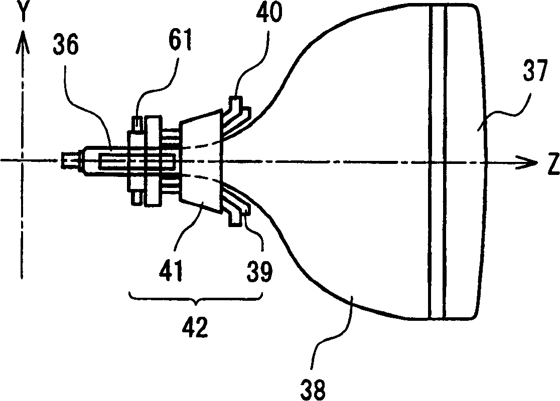
[0037] Hereinafter, a cathode ray tube device according to an embodiment of the present invention will be described with reference to the drawings. figure 1 It is a plan view of the cathode ray tube device according to the embodiment of the present invention.

[0038] figure 1 Among them, the cathode ray tube body 36 is composed of a glass panel 37 and a glass funnel 38 connected to the rear of the glass panel 37 . On the rear portion of the cathode ray tube body 36, an electron gun is provided. Moreover, on the rear portion outer periphery of the cathode ray tube body 36, a horizontal deflection coil 39 wound into a saddle shape, a saddle-type vertical deflection coil 40 disposed on the outside of the horizontal deflection coil 39, and a vertical deflection coil 40 disposed on the outside of the vertical deflection coil 40 are installed. The ferrite core 41 on the outer side constitutes the deflection yoke 42 .

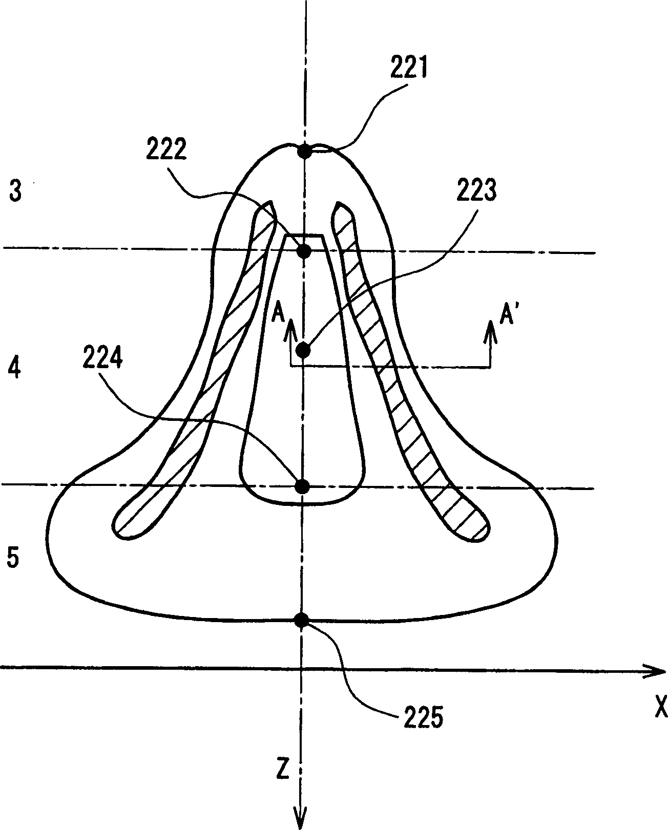
[0039] figure 2 The drawing of the horizontal deflection c...


PUM


Abstract

A horizontal deflection coil is formed by winding conductive wires. A wire density of the conductive wires in a first portion of the horizontal deflection coil, which is defined in a predetermined angle range centering on a winding angle, and which is set to be theta1 with respect to a horizontal direction as 0 DEG in an electron-gun-side region, theta2 with respect to a horizontal direction as 0 degree in a middle region, and theta3 with respect to a horizontal direction as 0 degree in a screen-side region on a cross section perpendicular to a tube axis, is smaller than a wire density of the conductive wires in a portion of the horizontal deflection coil other than the first portion. The winding angles theta1, theta2, and theta3 in the first portion satisfy theta1>=theta2>=theta3. With this configuration, it is possible to provide a cathode-ray tube device in which, without an additional correcting coil or a specific correcting circuit for generating a correcting current, the dynamic convergence adjustment is facilitated, and an excellent convergence characteristic is achieved.

Description

technical field [0001] The present invention relates to a cathode ray tube device. In particular, it relates to a cathode ray tube device having improved convergence characteristics of a deflection yoke. Background technique [0002] As the OS of personal computers, with the spread of multi-screen display environments such as Microsoft Windows, etc., in cathode ray tube devices used in computer monitors, high resolution at the periphery of the screen has become an important technology topic. [0003] As one of the factors determining the resolution, there may be mentioned convergence characteristics representing aberration errors (hereinafter referred to as "misconvergence") of electron beams for blue, green, and red light emission on the screen surface. [0004] In the cathode ray tube device for display, the misconvergence on the screen surface is adjusted to about 0.25 mm in the manufacturing process. In this case, especially at the corners of the screen surface, it is...

Claims


Application Information

Patent Timeline
Patent Type & Authority Applications(China)
IPC IPC(8): H01J29/76H01J29/70
CPCH01J2229/7035H01J29/705H01J29/76
Inventor 杉本一宏
Owner PANASONIC CORP
Why Eureka
Try Eureka