Active flexible force control device

A technology for controlling equipment and flexible force, applied in the direction of torque/mechanical power control, non-electric variable control, control/regulation system, etc. Applicable and other issues, the load range can be easily adjusted, the self-weight and load can be overcome, and the dynamic response speed is fast.

Active Publication Date: 2017-08-29
INST OF INTELLIGENT MFG GUANGDONG ACAD OF SCI
View PDF20 Cites 1 Cited by
  • Summary
  • Abstract
  • Description
  • Claims
  • Application Information

AI Technical Summary

Problems solved by technology

Most of the force control technologies used in the market are passive force control, which can only realize force control in a single environment, without versatility and intelligence
[0003]The cost of using the cylinder as the drive is relatively low, and it is very suitable for low-speed applications that do not require high force control. The disadvantage is that the output force will There is a relatively long hysteresis, which cannot be applied to a relatively high-speed environment
When using a six-axis general-purpose robot, the torque output of each joint motor is controlled according to the force feedback of the end force sensor. The accuracy and speed are good. The disadvantage is that the cost is very high. It is tried for high-end automation equipment, and the cost is too high for low-end automation applications.
[0004]Secondly, the existing equipment still has the following problems: 1) The force control of the existing equipment is not universal; 2) The influence of the self-weight on the end of the force control has not been eliminated; 3) Due to the influence of the terminal's own weight, only force control in a fixed direction can be achieved (except for six-axis robots using force sensors)

Method used


Image

  • Active flexible force control device
  • Active flexible force control device
  • Active flexible force control device

Examples


Embodiment

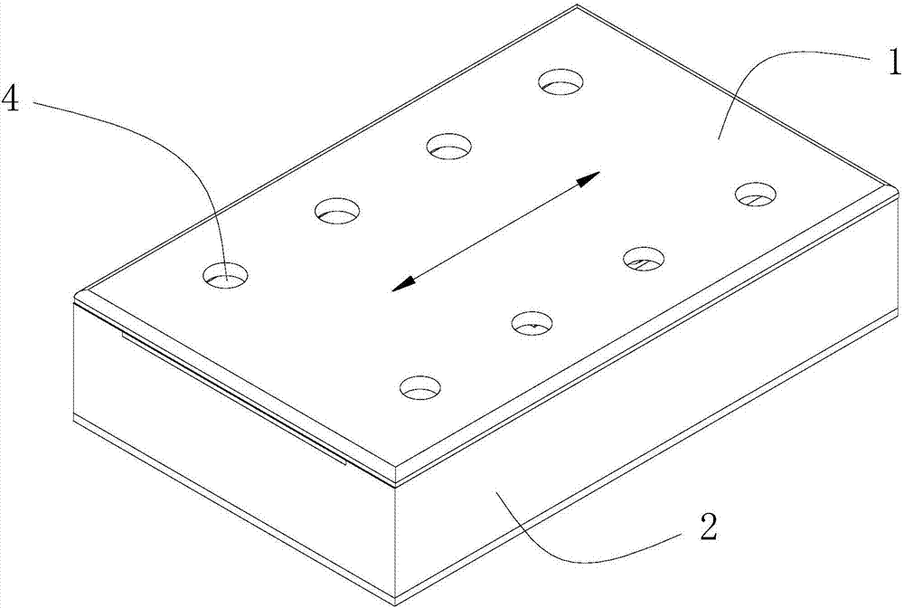
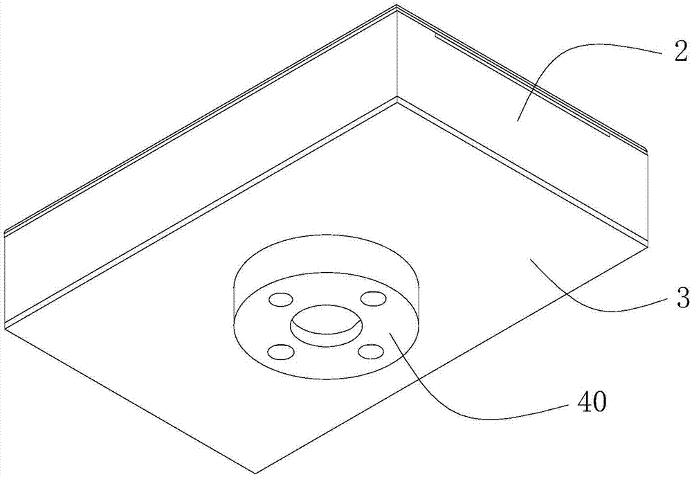
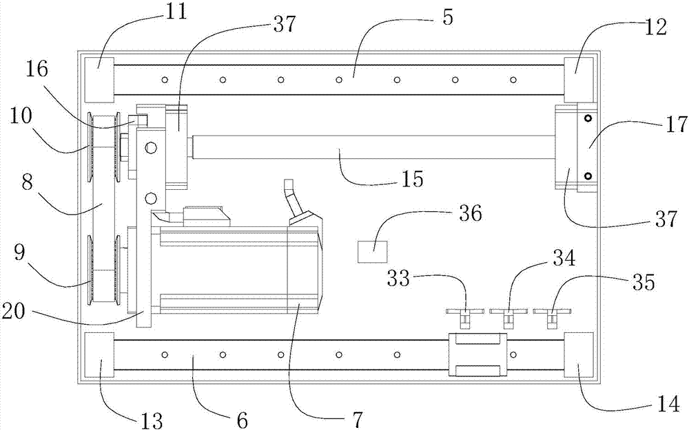
[0036] refer to Figure 1 to Figure 16 , is an active flexible force control device, which includes a force control body, the force control body includes an upper cover 1, a protective cover 2 and a bottom plate 3, the protective cover 2 is arranged around the periphery of the bottom plate 3, and the upper cover 1 seals the protective cover 2 On the upper side, the bottom plate 3 seals the lower side of the protective cover 2; the force control body is provided with a fixed mechanism, an intermediate motion connection mechanism and a motion platform mechanism; the intermediate motion connection mechanism is arranged on the fixed mechanism and slides along it, and the motion platform mechanism is set On the lower side of the upper cover 1 and the moving platform mechanism can slide along the fixed mechanism; the upper cover 1 is provided with a threaded hole 4, and the force control object to be controlled is installed on the force control body through the threaded hole 4; the f...


PUM


Abstract

The present invention discloses an active flexible force control device comprising a force control body including an upper cover, a shield and a bottom plate. The force control body is internally provided with a fixing mechanism, an intermediate movement connecting mechanism and a moving platform mechanism. The intermediate movement connecting mechanism is arranged on and slides along the fixing mechanism, and the moving platform mechanism is arranged on the lower side of the upper cover and the moving platform mechanism is slidable along the fixing mechanism. The upper cover is provided with a screw hole, and a force control object to be controlled is installed on the force control body through the screw hole. The force control body is also provided with a linear grating sensor for detecting the position change of the moving platform mechanism. The device cost is low, the versatility is strong, the installation is flexible and easy, and the control body can install various custom tools to carry on the force control. The dynamic response speed is fast and the force control precision is high. A servo motor is adopted to form a fully-closed loop with the linear grating sensor and an inclination angle sensor, the deadweight and load can be overcome, and the two-way force control and load range can be adjusted easily.

Description

technical field [0001] The invention relates to the technical field of industrial equipment, in particular to an active flexible force control equipment. Background technique [0002] Active flexible force control refers to the ability to simultaneously control the output force of the moving components during the movement of the mechanism. In the field of automation and robot applications, active force control technology is one of the key technologies that need to be used in many application scenarios, such as automatic polishing, automatic grinding and automatic assembly. Most of the existing solutions in this type of application use the cylinder as the drive to control the output force by controlling the internal pressure. Another solution in the application of robotics is to use a six-axis universal robot with a force sensor installed at its end. According to Force feedback is used to control the output torque of each joint motor, and then control the size of the end con...

Claims


Application Information

Patent Timeline
Patent Type & Authority Applications(China)
IPC IPC(8): G05D17/02
CPCG05D17/02
Inventor 李凯格蔡奕松周雪峰程韬波
Owner INST OF INTELLIGENT MFG GUANGDONG ACAD OF SCI
Why Eureka
Try Eureka