
Novel resistor installer

A mounter and resistor technology, applied in the direction of resistor installation/support, resistor terminal/electrode, device to prevent contact with live contacts, etc. To achieve the effect of convenient repeated installation and use, improve the safety of use, and prevent accidental electric shock

Active Publication Date: 2017-08-29
江苏双兴工贸有限公司
View PDF4 Cites 3 Cited by
  • Summary
  • Abstract
  • Description
  • Claims
  • Application Information

AI Technical Summary

Problems solved by technology

The installation method of the existing resistors is generally connected in series on the wires. The connection method is not stable, and the connectors are often loose and cannot work normally. At the same time, because the terminals of the existing resistors are often exposed to the outside world, it is easy to It leads to the instability of power supply, and also increases the probability of maintenance personnel accidentally touching it during maintenance and maintenance, which will cause electric shock, and there are certain potential safety hazards.

Method used


Image

  • Novel resistor installer
  • Novel resistor installer
  • Novel resistor installer

Examples


Embodiment Construction

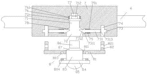
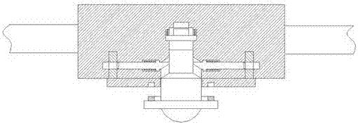
[0022] Such as Figure 1-Figure 5 As shown, a new resistance installer of the present invention includes a wire 6, a series seat 7 and a resistance component 8 used to cooperate with the series seat 7, and the series seat 7 is connected in series at the middle end of the wire 6 Two sets of suction cups 70 are evenly arranged on the rear end surface of the series seat 7 in the up and down direction, and the suction cups 70 are used to absorb and fix the series seat 7, so that the device is more stable during operation. The end is provided with a first sliding groove 71, the bottom of the first sliding groove 71 is provided with a second sliding groove 72, and the inner top wall of the series seat 7 on the top of the first sliding groove 71 is provided with There is an electrification chamber 77, and the inner wall of the series seat 7 on both sides of the first sliding groove 71 is provided with a first sliding groove 76, and a pressing plate 711 is slidingly fitted in the firs...


PUM


Abstract

The invention discloses a novel resistor installer. The novel resistor installer comprises a lead, a serial seat and a resistor part for being connected with the serial seat in a matching manner, wherein the serial seat is serially connected to the middle end of the lead; two groups of suckers are uniformly arranged on the rear end face of the serial seat in upper and down directions; a first sliding groove is formed in the middle end in the serial seat; a second sliding groove is formed in the lower side of the bottom end of the first sliding groove; an energizing chamber is arranged on the top wall in the serial seat on the upper side of the first sliding groove; another first sliding grooves are formed in the inner side walls of the serial seat on two sides of the first sliding groove; a pressing plate is in sliding matched connection with the inner parts of the another first sliding grooves; an energizing rod arranged by corresponding to the energizing chamber is arranged at the top end of the pressing plate; first compressed springs are arranged at the top end of the pressing plate in the another first sliding grooves; a clamping groove is formed between the first sliding groove and the second sliding groove. The novel resistor installer disclosed by the invention has the advantages of simple structure, convenience in installation, high stability after installation and simplicity and convenience in replacement; accident electric shock is prevented, so that the safety is improved.

Description

technical field [0001] The invention relates to the technical field of electric equipment, in particular to a novel resistance installer. Background technique [0002] Resistors are electronic components that hinder current flow, and are often used in some electrical equipment. The installation method of the existing resistors is generally connected in series on the wires. The connection method is not stable, and the connectors are often loose and cannot work normally. At the same time, because the terminals of the existing resistors are often exposed to the outside world, it is easy to This leads to the instability of the power supply, and also increases the probability of maintenance personnel accidentally touching and causing electric shock during the inspection and maintenance time, posing certain safety hazards. Contents of the invention [0003] The technical problem to be solved by the present invention is to provide a novel resistor installer, which can solve the ...

Claims


Application Information

Patent Timeline
Patent Type & Authority Applications(China)
IPC IPC(8): H01C1/01H01C1/14H01R13/639H01R13/44
CPCH01C1/01H01C1/14H01R13/44H01R13/639
Inventor 林金杰
Owner 江苏双兴工贸有限公司
Learn More