Electrical connector combination

A technology for electrical connectors and docking spaces, which is applied in the field of electrical connector combinations that can be plugged in and out. It can solve the problems of signal chip burnout, ground shrapnel short circuit, ground shrapnel cannot be grounded, etc., to avoid short circuit and good electrical connection Effect

Active Publication Date: 2017-08-29
DEYI PRECISION ELECTRONIC IND CO LTD PANYU
View PDF4 Cites 50 Cited by
  • Summary
  • Abstract
  • Description
  • Claims
  • Application Information

AI Technical Summary

Problems solved by technology

When the docking connector is first inserted into the plug-in space, because the plastic body protrudes out of the shielding shell, the shielding shell cannot immediately contact the metal shell to ground the shielding shell, so the grounding shrapnel cannot be grounded immediately after the docking connector. Promptly ground when starting to plug into the mating space
Because there is a gap when the butt connector and the electrical connector are inserted into each other, the butt connector is easily inserted into the insertion space, and the ground shrapnel is easy to contact the signal terminal to cause a short circuit, which in turn causes the signal chip on the circuit board to burn. Bad, seriously affecting the electrical connection of the electrical connector and the mating connector

Method used


Image

  • Electrical connector combination
  • Electrical connector combination
  • Electrical connector combination

Examples


Embodiment Construction

[0043] In order to facilitate a better understanding of the purpose, structure, features, and effects of the present invention, the present invention will now be further described in conjunction with the accompanying drawings and specific embodiments.

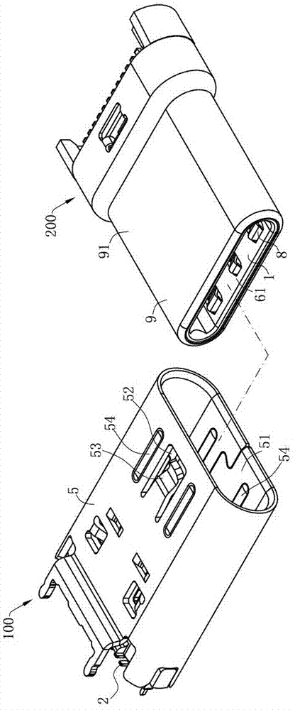
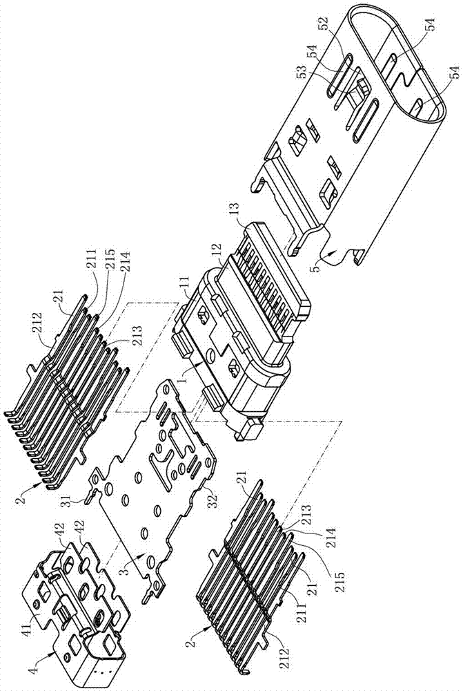
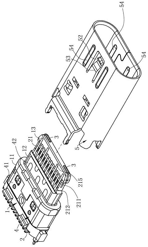
[0044] Such as figure 1 , Figure 7 and Figure 8 The electrical connector assembly of the present invention includes an electrical connector 100 and a pair of mating connectors 200 that are mutually docked with the electrical connector 100, wherein the electrical connector 100 includes an insulating body 1, and the insulating body 1 has a base 11 and a self-contained body. A tongue plate 13 extending forward from the base 11, a plurality of first terminals 2 are fixed on the base 11 and extend into the tongue plate 13, the plurality of first terminals 2 include at least one first signal terminal 211, a metal shell 5 is sleeved outside the base 11 and the tongue plate 13, and the butt connector 200 includes a plastic seat bod...


PUM


Abstract

The invention discloses an electrical connector combination. The electrical connector combination comprises an electrical connector and an abutting connector, wherein the electrical connector comprises a base and a tongue plate, the tongue plate forwards extends from the base, a first signal terminal is fixedly arranged on the base and is exposed on a surface of the tongue plate, an insertion space is formed between a metal shell and the tongue plate, the abutting connector comprises a plastic seat, a second signal terminal is fixedly arranged on the plastic seat and extends and enters an abutting space, a grounding elastic sheet is fixedly arranged on a wall part and is in contact with a shielding shell, the electrical connector and the abutting connector are provided with a first abutting state and a second abutting state when the electrical connector and the abutting connector are abutted along an abutting direction, in the first abutting state, the shielding shell partially enters the insertion space and communicates with the metal shell, a gap is formed between the grounding elastic sheet and the first signal terminal, and the second signal terminal is not in contact with the first signal terminal, and in the second abutting state, the tongue plate is inserted into the abutting space, the shielding shell communicates with the metal shell, and the second signal terminal is in contact with the first signal terminal.

Description

technical field [0001] The invention relates to an electric connector combination, in particular to an electric connector combination which can be plugged in front and back. Background technique [0002] With the development of the electronic industry, the requirements for the plugging and unplugging performance of the interface type electrical connector combination are also gradually increased, so as to meet the needs of the market. The existing electrical connector combination includes a mutually butted electrical connector and a butt connector, wherein the electrical connector is installed on a circuit board, includes an insulating body, the insulating body has a tongue plate, and a plurality of signal terminals are fixed on the insulating body and Exposed on the surface of the tongue plate, a metal shell covers the periphery of the tongue plate to form a plug-in space. The docking connector includes a plastic body, a plurality of butt terminals fixed on the plastic body,...

Claims


Application Information

Patent Timeline
Patent Type & Authority Applications(China)
IPC IPC(8): H01R13/648H01R13/502H01R13/516H01R13/02H01R24/00
CPCH01R13/02H01R13/502H01R13/516H01R13/648H01R24/00H01R13/6583H01R13/6593H01R24/60
Inventor 朱德祥
Owner DEYI PRECISION ELECTRONIC IND CO LTD PANYU
Why Eureka
Try Eureka