Stent and stent graft

A stent-graft and fabric technology, applied in the field of tubular organs, can solve the problems of poor followability of curved shape and poor diameter reduction.

Active Publication Date: 2017-08-29
JAPAN LIFELINE CO LTD
View PDF4 Cites 1 Cited by
  • Summary
  • Abstract
  • Description
  • Claims
  • Application Information

AI Technical Summary

Problems solved by technology

[0013] Therefore, the stent described in the above-mentioned Patent Document 1 has poor followability to a curved shape and poor diameter shrinkability.

Method used


Image

  • Stent and stent graft
  • Stent and stent graft
  • Stent and stent graft

Examples


no. 1 approach >

[0073] Hereinafter, specific embodiments of the present invention will be described in detail.

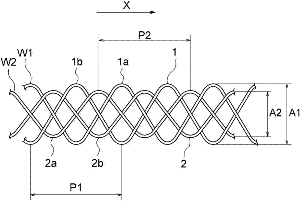
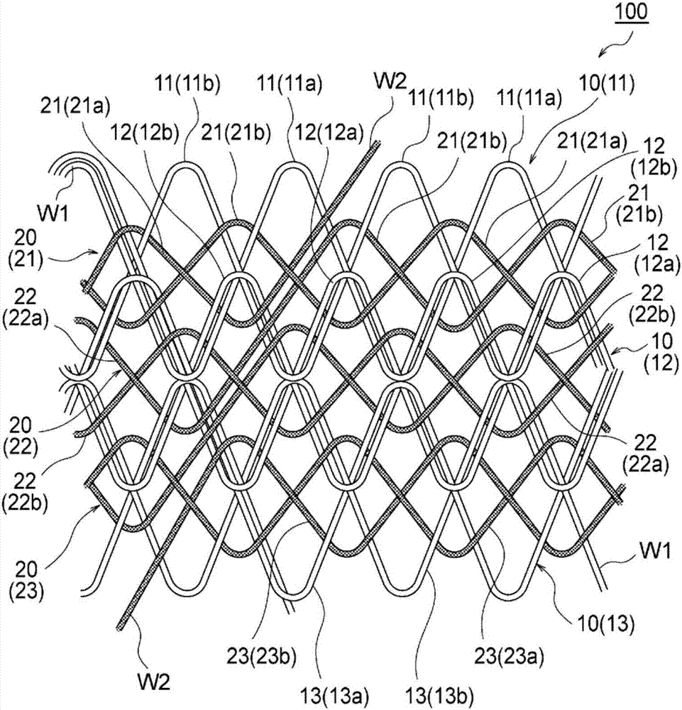
[0074] figure 2 The stent 100 of the present embodiment shown is constituted by: a first fabric structure 10 consisting of a first layer of circumferential cells 11 , a second layer of circumferential cells 12 , and a third layer of circumferential cells 13 adjacent to each other. The circumferential units of each have overlapping parts and are arranged in the axial direction; the second fabric structure 20 is composed of the circumferential unit 21 of the first layer, the circumferential unit 22 of the second layer and the circumferential direction of the third layer The units 23 are arranged axially without overlapping adjacent circumferential units.

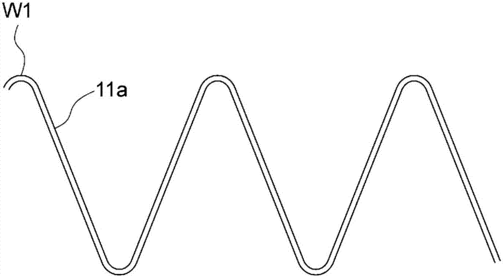
[0075] The circumferential unit 11 constituting the first layer of the first fabric structure 10 is formed by a first loop 11a and a second loop 11b, and the first loop 11a is formed by turning the wire W1 back and forth to the l...

no. 2 approach >

[0112] Figure 4 as well as Figure 5 The stent 200 of the present embodiment shown is constituted similarly to the stent 100 of the first embodiment: a first fabric structure 10 ′, which consists of a first-layer circumferential unit 11 ′, a second-layer circumferential unit 12' and the circumferential unit 13' of the third layer are arranged in the axial direction; the second fabric structure 20' is formed by combining the circumferential unit 21' of the first layer, the circumferential unit 22' of the second layer and The circumferential units 23' of the third layer are arranged along the axial direction.

[0113] In addition, in Figure 5 in, will Figure 4 In the structure shown with figure 2 The parts where the structures shown are different (in the intersecting part of the wire W1 constituting the first fabric structure and the wire W2 constituting the second fabric structure, the front-rear relationship of the wire W1 and the wire W2 is the same as figure 2 The ...

no. 3 approach >

[0123] Figure 6 The shown bracket 300 of this embodiment is composed of a first fabric structure 60 and a second fabric structure 70, and the first fabric structure 60 is formed by combining the circumferential unit 61 of the first layer and the circumferential unit 61 of the second layer. The units 62 are arranged in the axial direction, and the second fabric structure 70 is formed by arranging the circumferential units 71 of the first layer and the circumferential units 72 of the second layer in the axial direction.

[0124] Each of the circumferential units ( 61 , 62 , 71 , 72 ) is composed of two rings that intersect each other in a cross at each linear portion, and one ring advances up and down alternately passing through the other ring.

[0125] Such as Figure 6 As shown, the circumferential unit 61 of the first layer and the circumferential unit 62 of the second layer constituting the first fabric structure 60 are staggered by one pitch (swing width) in the axial dir...


PUM


Abstract

The present invention addresses the problem of providing a stent that can be designed to have a small mesh size without sacrificing diameter reducing properties and conformability to a curved shape, and is capable of preventing, when placed in a tubular organ, restenosis caused by intrusion of a tumor tissue into the lumen. The stent according to the present invention is configured from: a first weave structure (10) in which circumferential units (11-13) each comprising a plurality of circumferentially arranged mesh openings are disposed in the axial direction; and a second weave structure (20) in which circumferential units (21-23) each comprising a plurality of circumferentially arranged mesh openings are disposed in the axial direction to correspond to the circumferential units (11-13) of the first weave structure (10). The circumferential units of the second weave structure (20) are offset by 1/4 of the pitch in the circumferential direction relative to the corresponding circumferential units of the first weave structure, and interwoven with the corresponding circumferential units of the first weave structure. The second weave structure (20) is configured so that the bending part of one of each pair of adjacent circumferential units thereof is not interlocked with the bending part or wire intersection of the other circumferential unit.

Description

technical field [0001] The present invention relates to a stent and a stent graft for preventing stenosis and blockage of a tubular organ by indwelling the tubular organ in a digestive tract or the like. Background technique [0002] A stent placed in the digestive tract (digestive tract stent) is used to expand the lumen of the digestive tract narrowed by a tumor. [0003] Such a stent for the digestive tract is required to have a high expansion force for sufficiently expanding the stenosis, good diameter constriction for smooth insertion into the delivery sheath, and good followability to the curved shape of the digestive tract. [0004] However, there are cases where, after the stent is placed in the digestive tract, tumor tissue invades the lumen of the stent from the mesh of the stent due to the growth of the tumor, resulting in narrowing of the gastrointestinal tract again. [0005] In order to prevent such restenosis of the digestive tract, it is desirable to make th...

Claims


Application Information

Patent Timeline
Patent Type & Authority Applications(China)
IPC IPC(8): A61F2/90A61F2/07A61F2/844
CPCA61F2/90A61F2/07A61F2002/045A61F2210/0076
Inventor 中野英一小林史明
Owner JAPAN LIFELINE CO LTD
Why Eureka
Try Eureka