
Valve device in a motor vehicle, and production method

A valve device and motor vehicle technology, applied in the field of manufacturing, can solve problems such as high cost and complicated valve device structure, and achieve the effect of low leakage rate and long-lasting sealing

Inactive Publication Date: 2017-08-29
CONTINENTAL AUTOMOTIVE GMBH
View PDF4 Cites 1 Cited by
  • Summary
  • Abstract
  • Description
  • Claims
  • Application Information

AI Technical Summary

Problems solved by technology

This has the result that such a valve arrangement is complex in construction and therefore relatively expensive

Method used


Image

  • Valve device in a motor vehicle, and production method
  • Valve device in a motor vehicle, and production method
  • Valve device in a motor vehicle, and production method

Examples


Embodiment Construction

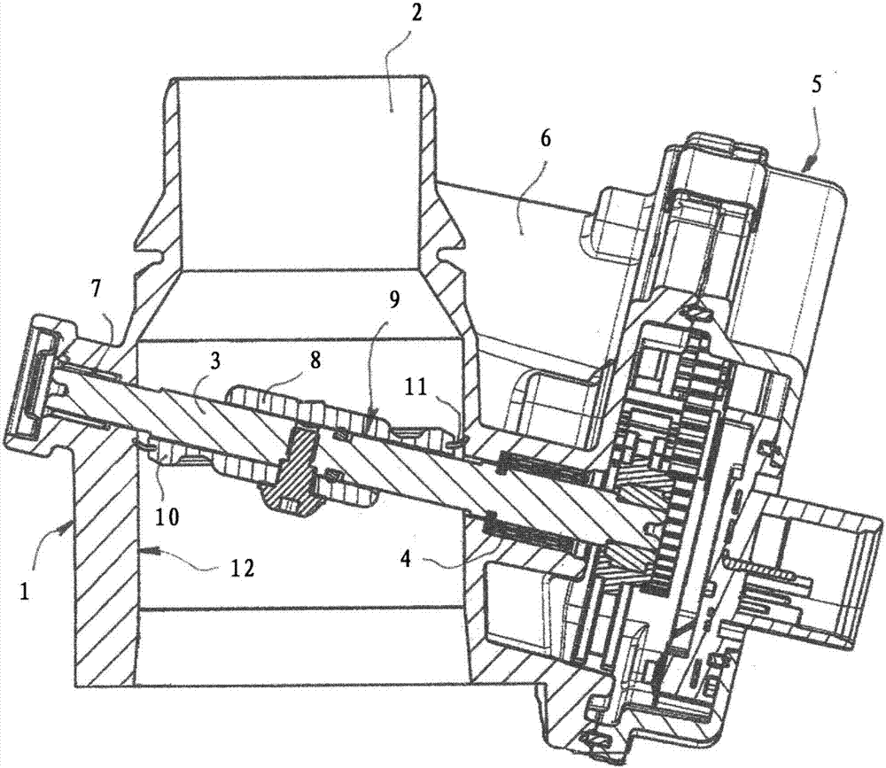
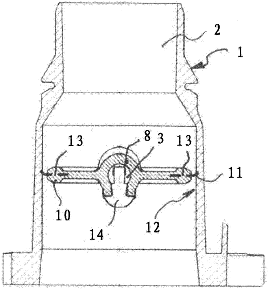
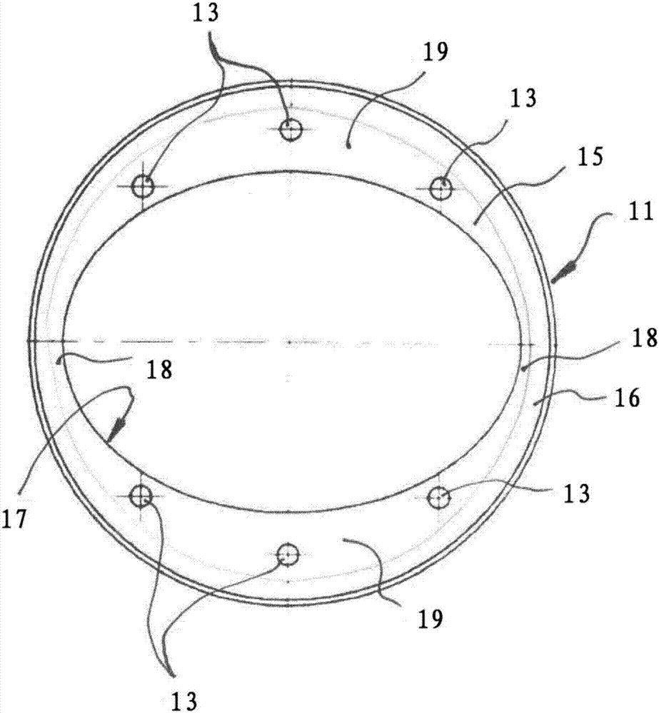
[0026] figure 1 The valve arrangement for a motor vehicle in ® consists of a housing 1 with a flow channel 2 arranged in the housing for the flow of a fluid. In the present case, the air flow is regulated by means of valve means. Arranged in the flow channel 2 is a shaft 3 , which is supported on both sides in the housing 1 . The first bearing 4 is located on that side of the housing 1 on which the transmission 5 is arranged. The transmission 5 is connected on the output side to the shaft 3 and on the input side to an electric motor, not shown, which is accommodated in a separate chamber 6 of the housing 1 . The second bearing 7 for the shaft 3 is located on the side of the flow channel 2 opposite the transmission 5 . Arranged on the shaft 3 is a flap 8 which has a bore 9 through which the shaft 3 extends. In order to be fixed on the shaft 3, the disc 8 is screwed to the shaft 3. The valve flap 8 also has a circumferentially surrounding edge 10 on which a seal 11 is arran...


PUM


Abstract

The invention relates to a valve device for a fuel cell arrangement in a motor vehicle, having a flow duct (2) which runs in a housing (1), having a flap (8) which influences the flow cross section, and having a drive which drives the flap, wherein the flap is fastened to a spindle (3) and the spindle is mounted rotatably in the housing, having a valve seat (12) which is arranged in the flow duct, and having a seal (11) which is arranged on a radially encircling edge (10) of the flap and which, in a closed position of the flap, is in contact with the valve seat such that the spindle extends through the flap at an angle. The seal has a ring-shaped main body (15) which has at least one recess (13), wherein the at least one recess is filled with the material of the flap.

Description

technical field [0001] The invention relates to a valve device for a fuel cell arrangement / device in a motor vehicle, having: a flow channel extending in a housing; a valve flap influencing the flow section / cross section; and a drive device for driving the valve flap, Therein, the valve flap is fixed on a shaft and the shaft is rotatably supported in the housing; a valve seat is arranged in the flow channel; and a seal is arranged on the circumferentially surrounding edge of the valve flap , the seal is in contact with the valve seat in the closed position of the valve flap such that the shaft passes through the valve flap at an angle. The invention also relates to a manufacturing method. Background technique [0002] Such valve arrangements have been known for a long time and therefore belong to the prior art. Due to the flowing medium, for example air, the control element must be able to achieve a high degree of tightness when closing the flow channel. Furthermore, thes...

Claims


Application Information

Patent Timeline
Patent Type & Authority Applications(China)
IPC IPC(8): F16K1/226
CPCF16K1/2261H01M8/04014H01M2250/20H01M8/04Y02E60/50Y02T90/40Y02P70/50B29C45/2608B29L2031/7506F16K25/005
Inventor R·J·蒙蒂尼P·科伦
Owner CONTINENTAL AUTOMOTIVE GMBH
Learn More