Target path generation device and travel control device
一种目标路径、生成装置的技术,应用在控制装置、道路车辆的交通控制系统、车辆位置/路线/高度控制等方向,能够解决使用者乘坐的感觉不适感等问题,达到抑制不适感的效果
- Summary
- Abstract
- Description
- Claims
- Application Information
AI Technical Summary
Problems solved by technology
Method used
Image

Examples
no. 1 approach
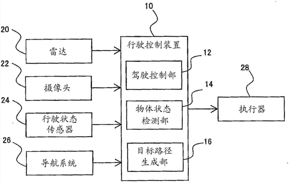
[0026] refer to figure 1 The configuration of the travel control device 10 according to the first embodiment will be described. figure 1 It is a block diagram showing the configuration of the travel control device according to the first embodiment. The travel control device 10 is a device mounted on a vehicle, and is a device for controlling automatic travel of the vehicle.
[0027] Such as figure 1 As shown, a radar 20 , a camera 22 , a driving state sensor 24 , a navigation system 26 , and an actuator 28 are electrically connected to the driving control device 10 . The travel control device 10 may also have other appropriate known configurations, for example, it may be connected to a communication unit for inter-vehicle communication.
[0028] The radar 20 detects the presence, position, and speed of vehicles, motorcycles, bicycles, pedestrians, etc. around the own vehicle, and their relative speeds with respect to the own vehicle. The radar 20 includes, for example, a l...
no. 2 approach
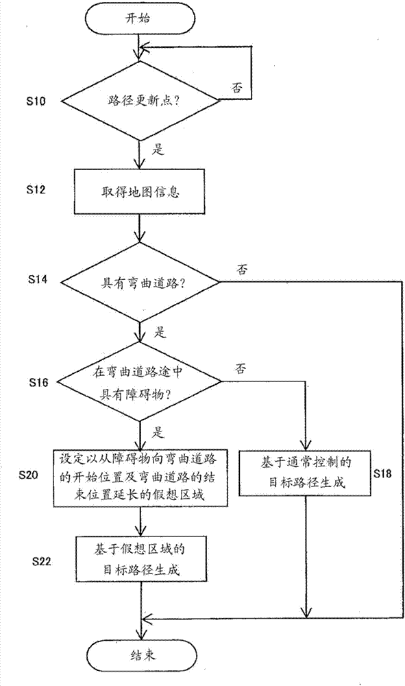
[0062] Next, refer to Figure 5 and Figure 6 The travel control device 10 of the second embodiment will be described. Figure 5 It is a flowchart showing the generation process of the target route of the curved road in the second embodiment. Figure 6 It is a diagram showing the road layout of the curved road and the target trajectory of the vehicle in the second embodiment. In the second embodiment, the point related to the generation of the target route when there is a physical obstacle on the front side of the curved road 68 in the traveling direction and within a predetermined distance from the end point of the curved road 68 is similar to that of the first embodiment. different. In addition, the same code|symbol is attached|subjected to the same structure as 1st Embodiment, and redundant description is abbreviate|omitted.
[0063] Such as Figure 6 As shown, in the second embodiment, it is illustrated that the map information obtained when generating the target rout...
no. 3 approach
[0077] Next, a travel control device 10 according to a third embodiment will be described. In the third embodiment, the method of detecting a physical obstacle when generating a target route is different from that in the first embodiment. That is, the obstacle determination unit 34 does not determine whether there is an object to avoid based on the map information, but acquires surrounding information of the detected vehicle and determines whether there is an object to avoid. The configurations other than that are the same as those of the first embodiment, and therefore the same symbols are attached to the same configurations, and overlapping descriptions are omitted.
[0078]In the third embodiment, physical obstacles are detected by the radar 20 and the camera 22 instead of the map information stored in the navigation system 26 . Specifically, the object state detection unit 14 uses data detected by the radar 20 and images around the vehicle captured by the camera 22 to det...
PUM
 Abstract
Description
Claims
Application Information
 - R&D
- Intellectual Property
- Life Sciences
- Materials
- Tech Scout
- Unparalleled Data Quality
- Higher Quality Content
- 60% Fewer Hallucinations
Browse by: Latest US Patents, China's latest patents, Technical Efficacy Thesaurus, Application Domain, Technology Topic, Popular Technical Reports.
© 2025 PatSnap. All rights reserved.Legal|Privacy policy|Modern Slavery Act Transparency Statement|Sitemap|About US| Contact US: help@patsnap.com