Laminated core structure, and transformer including the laminated core structure
一种叠铁芯、构造体的技术,应用在变压器、固定变压器、变压器/电感器磁芯等方向,能够解决无法制造大容量变压器的铁芯等问题
- Summary
- Abstract
- Description
- Claims
- Application Information
AI Technical Summary
Problems solved by technology
Method used
Image

Examples
Embodiment 1
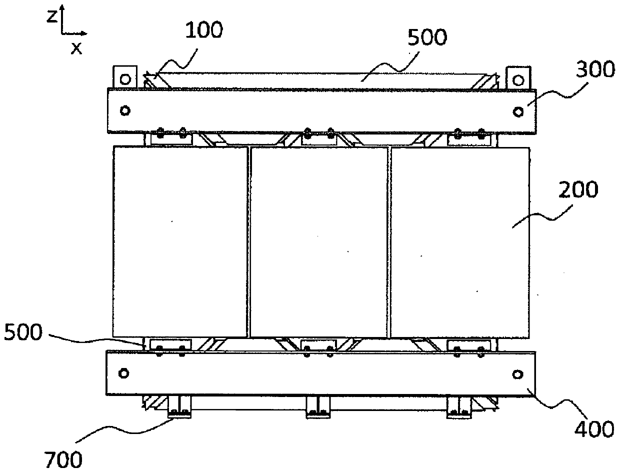
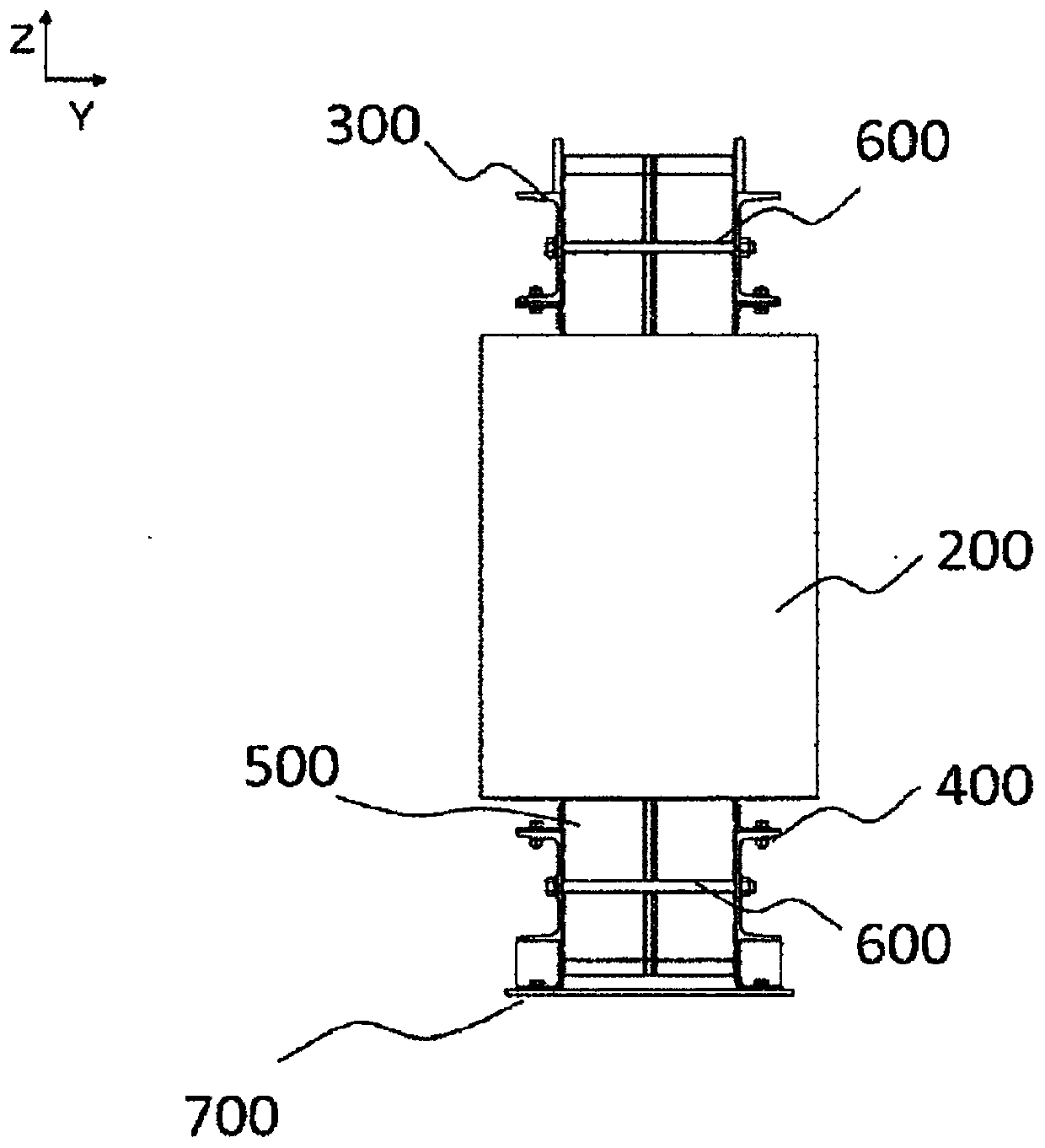
[0032] use Figure 1~6 , to illustrate Embodiment 1 of the present invention. exist figure 1 , figure 2 The body structure of the transformer of Example 1 is described in . figure 1 is the front view, figure 2 is a side view. The body structure of the transformer of the present invention includes an iron core 100 , a coil 200 , an upper fastening metal part 300 , a lower fastening metal part 400 , an iron core fixing metal part 500 , a fastening metal part tightening bolt 600 , and a base 700 . The iron core fixing metal fitting 500 is a cylindrical member having a quadrangular cross-section surrounding the laminated iron core 100 and is disposed so as to pass through the coil 200 . In addition, the iron core 100 arranged in the iron core fixing metal fitting 500 is fixed by tightening the upper fastening metal fitting 300 and the lower fastening metal fitting 400 with the fastening metal fitting tightening bolt 600 . Furthermore, the core fixing metal fitting 500 is f...
Embodiment 2
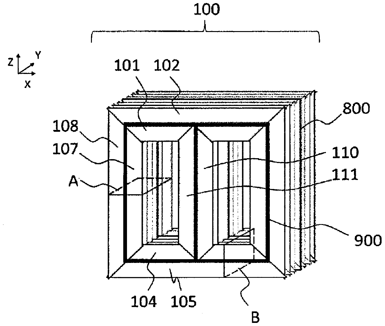
[0051] Figure 7 A front view of the iron core 100 in the second embodiment of the present invention is shown. with the first embodiment Figure 3d Similarly, two core laminates such as core materials 107 and 108 , 101 and 102 , and 104 and 105 are arranged side by side, and a first laminate block and a second laminate block are laminated. The difference from the first embodiment is that the material widths of the core materials 107 and 108 are different from each other. Similarly, 101 and 102, 104 and 105 also have different material widths. In the central core part of the three-legged core legs, laminated blocks of the core material 110 having a small material width and laminated blocks of the core material 111 having a large material width are arranged side by side, and they are similar to those of the first embodiment. The examples are similarly stacked with right and left reversed for each stacked block. In the case of the second embodiment, the core material 111 havi...
Embodiment 3
[0057] Figure 8 A front view of the iron core 100 in the third embodiment of the present invention is shown. with the first embodiment Figure 3d and the second embodiment Figure 7 Similarly, two core laminates such as core materials 107 and 108 , 101 and 102 , and 104 and 105 are arranged side by side, and a first laminate block and a second laminate block are laminated. In this embodiment, the core materials 110 and 111 constituting the central core leg have the same width, while the core materials 107 and 108 constituting the outer core legs, the core material 101 and the Reference numeral 102 designates different core widths from each other. The central core leg is composed of two types of wide cores constituting the outer core leg. Iron core foot is big. Since the core leg in the center is sandwiched between the core legs and the coil 200 on both sides, it is easy to trap heat, but it is difficult to cool down compared to the core legs on both sides. When the iron...
PUM
 Abstract
Description
Claims
Application Information
 - R&D
- Intellectual Property
- Life Sciences
- Materials
- Tech Scout
- Unparalleled Data Quality
- Higher Quality Content
- 60% Fewer Hallucinations
Browse by: Latest US Patents, China's latest patents, Technical Efficacy Thesaurus, Application Domain, Technology Topic, Popular Technical Reports.
© 2025 PatSnap. All rights reserved.Legal|Privacy policy|Modern Slavery Act Transparency Statement|Sitemap|About US| Contact US: help@patsnap.com