Supercharge Your Innovation With Domain-Expert AI Agents!

Practical hot pot table

A hot pot table and practical technology, applied in the field of catering stoves, can solve the problems of hidden dangers, unfavorable cleaning of tabletop hygiene, occupation of tabletop position, etc., and achieve the effects of protecting nutrients, remarkable brewing effect, and protecting integrity

Inactive Publication Date: 2017-09-01
FUZHOU PINXING TECH DEV
View PDF0 Cites 3 Cited by
  • Summary
  • Abstract
  • Description
  • Claims
  • Application Information

AI Technical Summary

Problems solved by technology

[0002] Hot pot has a history of thousands of years in our country, and it is an integral part of our traditional food culture. Previously, the heating method of hot pot was mainly based on solid fuel heating methods such as charcoal; the existing hot pot heating method is mostly heated by electric heaters and gas. The disadvantage of the electric heating method is that the electric heating element is easily damaged and has a short life; charcoal, solid fuel and gas heating methods produce harmful gases that pollute the environment, and are inconvenient to use, especially the gas heating has the risk of explosion
Therefore, in the prior art, there is also a separate induction cooker as the heat source of the chafing dish to solve the above-mentioned defects, but there are still shortcomings, mainly that the induction cooker is placed on the dining table to occupy the tabletop position, and the chafing dish placed on it is in a higher position and is not convenient for eating. If you are not careful, it is easy to touch the hot pot, which is a hidden danger. At the same time, placing the induction cooker on the table is not conducive to cleaning the table. Since the induction cooker and the dining table are separated independently, when multiple induction cookers are placed, each induction cooker has a The power cord is connected to the outlet, which is messy and unsafe; it is also unsightly

Method used


Image

  • Practical hot pot table
  • Practical hot pot table
  • Practical hot pot table

Examples


Embodiment Construction

[0036] The present invention will be described in detail below in conjunction with the accompanying drawings and specific embodiments.

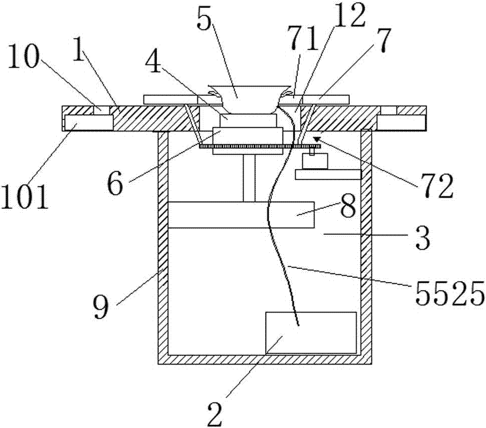
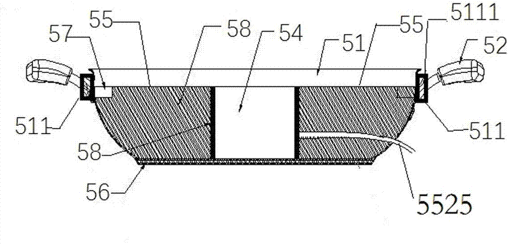
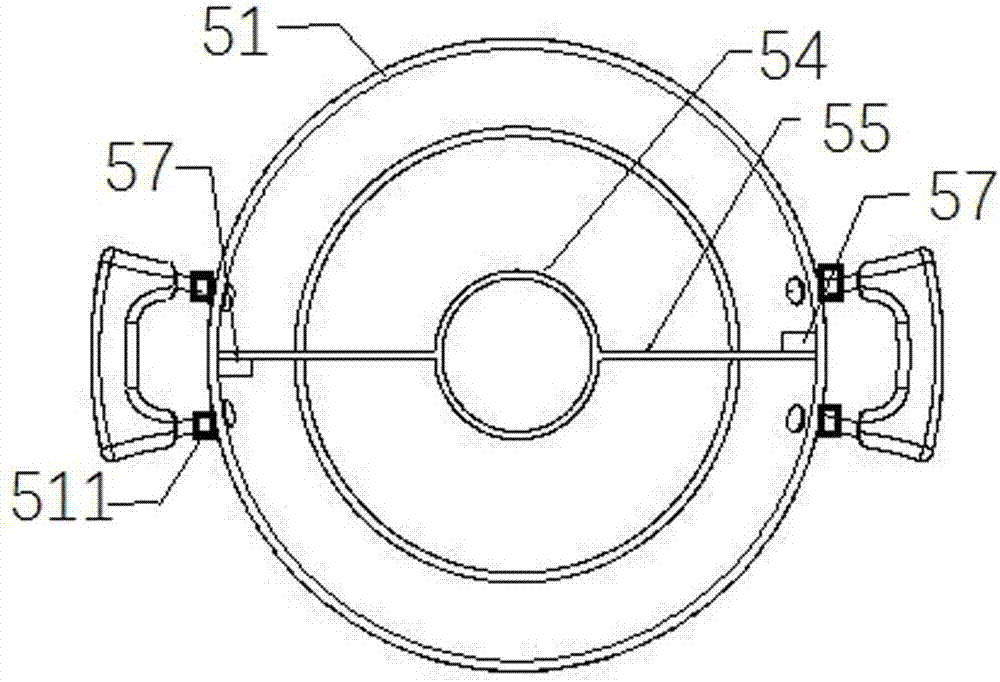
[0037] see Figure 1 to Figure 12, a practical hot pot table, comprising a desktop board 1 and a supporting table cabinet 9, the central position of the desktop board 1 is located on the supporting table cabinet 9, a hollow groove 3 is arranged inside the supporting table cabinet 9, and the center of the desktop board 1 corresponds to the hollow groove 3 A port 12 is opened; a chafing dish 5 and an electromagnetic heating furnace 4 are sequentially arranged in the hollow groove 3 from top to bottom; the chafing dish 5 is placed on the electromagnetic heating furnace 4, and the electromagnetic heating furnace 4 is driven up and down by a cylinder 8 arranged below it The chafing dish 5 comprises a stainless steel pot body 51 with a certain volume, pot ears 52, an annular partition 54 arranged at the center of the pot body 51, and two vertically...


PUM


Abstract

The invention relates to a practical hot pot table, which includes a desktop board and a supporting table cabinet. The central position of the tabletop board is located on the supporting table cabinet. A hollow groove is provided inside the supporting table cabinet. The center of the tabletop plate is opened corresponding to the hollow groove. There is a passage; a hot pot and an electromagnetic heating furnace are arranged in the hollow tank in sequence from top to bottom; the hot pot is placed on the electromagnetic heating furnace, and the electromagnetic heating furnace is driven up and down by a cylinder arranged below it; The hot pot includes a stainless steel pot body with a certain volume, pot ears, an annular partition arranged in the center of the pot body, and two vertically arranged flat partitions; a vertical side wall of the flat partition is connected to the pot body. The inner wall is connected, and the other vertical side wall is connected to the outer wall of the annular partition; there is a rectangular cavity inside the flat partition, and a water pretreatment device is installed in the rectangular cavity.

Description

technical field [0001] The invention relates to a practical hot pot table, which belongs to the technical field of catering stoves. Background technique [0002] Hot pot has a history of thousands of years in our country and is an integral part of our traditional food culture. Previously, the heating method of hot pot was mainly based on solid fuel heating methods such as charcoal; the existing hot pot heating method is mostly heated by electric heaters and gas. The disadvantage of the electric heating method is that the electric heating element is easily damaged and has a short life; charcoal, solid fuel and gas heating methods produce harmful gases that pollute the environment, and are inconvenient to use, especially the gas heating has the risk of explosion. Therefore, in the prior art, there is also a separate induction cooker as the heat source of the chafing dish to solve the above-mentioned defects, but there are still shortcomings, mainly that the induction cooker is...

Claims


Application Information

Patent Timeline
IPC IPC(8): A47B31/02A47B9/00A47B13/08A47B11/00
CPCA47B31/02A47B9/00A47B11/00A47B13/08A47B2031/023A47B2200/03
Inventor 池明霞郑德谋
Owner FUZHOU PINXING TECH DEV
Features
  • R&D
  • Intellectual Property
  • Life Sciences
  • Materials
  • Tech Scout
  • Unparalleled Data Quality
  • Higher Quality Content
  • 60% Fewer Hallucinations
Learn More