
Novel tracheal catheter device with infrared device and tooth pad

An infrared device and endotracheal catheter technology, which is applied in the direction of balloon catheter, endotracheal intubation, catheter, etc., can solve the problem that the position of the endotracheal catheter is not easy to monitor in real time, and achieve the effects of improving anesthesia safety, convenient operation, and simple design

Pending Publication Date: 2017-09-01
CANCER INST & HOSPITAL CHINESE ACADEMY OF MEDICAL SCI
View PDF12 Cites 0 Cited by
  • Summary
  • Abstract
  • Description
  • Claims
  • Application Information

AI Technical Summary

Problems solved by technology

[0007] In order to solve the problem that the position of the existing tracheal tube is not easy to monitor in real time, the present invention makes full use of the positional relationship between the dental pad and the tracheal tube and uses the dental pad to monitor the position of the tracheal tube. A new type of endotracheal tube device with dental pad

Method used


Image

  • Novel tracheal catheter device with infrared device and tooth pad
  • Novel tracheal catheter device with infrared device and tooth pad

Examples


Embodiment 1

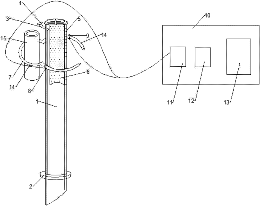
[0018] Example 1, from figure 1 It can be known that this new type of endotracheal tube device with an infrared device and a dental pad includes three parts: a catheter, an infrared device, and a dental pad 15. The catheter includes a catheter body 1, and the catheter body 1 adopts a single-lumen endotracheal tube. The lower end of 1 is provided with an inflatable bag 2, and the inflatable bag 2 is connected with an inflatable tube 3. The inflatable tube 3 runs along the inner body wall of the catheter body 1 from bottom to top, and extends out of the catheter body 1. At the end of the inflatable tube 3, an inflatable The valve 4 has length scale marks 5 from bottom to top on the outer wall of the catheter main body 1, and a coating 6 capable of absorbing infrared rays is coated on the inside of the lumen at the upper end of the catheter main body 1, and the coating 6 is coated on the upper end of the catheter main body On the inner wall of the lumen at the upper third, the de...

Embodiment 2

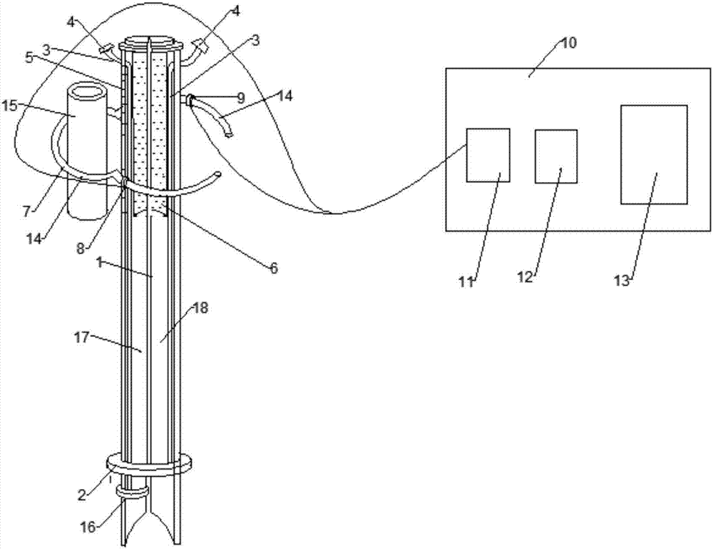
[0027] Example 2, from figure 2 It can be seen from the above that the difference between this embodiment and Embodiment 1 is that the catheter body 1 adopts a double-lumen endotracheal catheter, and the upper end of the catheter body 1 is provided with a part that can absorb infrared rays, which adopts a catheter at the upper end of the catheter body 1. There is a material capable of absorbing infrared rays inside the main body 1, and the material capable of absorbing infrared rays is integrated with the catheter body 1. This part is the upper third of the entire catheter body. The density of the infrared-absorbing material in the catheter body 1 increases with the The length scale marks 5 become larger from bottom to top, specifically, the density of the infrared-absorbing material in the catheter main body changes every 1 mm.

[0028] The catheter body 1 is a double-lumen endotracheal catheter, which means that the catheter body 1 has two catheters, the left one is the lef...


PUM


Abstract

The invention discloses a novel tracheal catheter device with an infrared device and a tooth pad. The novel tracheal catheter device comprises three parts including a catheter, the infrared device and the tooth pad, wherein the catheter comprises a catheter main body (1); the lower end of the catheter main body is provided with an inflating bag (2); a part capable of absorbing infrared rays is arranged at the upper end of the catheter main body (1); the infrared device is provided with a catheter fixing clamp (7); the catheter fixing clamp (7) comprises two arc-shaped fixing arms (14); only one end of the two fixing arms is connected; the two fixing arms of the catheter fixing clamp (7) have the elasticity; the fixing arms (4) are fixedly connected with the tooth pad (15); the tooth pad (15) is a hollow cylinder. The novel tracheal catheter device has the advantages that the design is simple; the prices is low; the operation is convenient; the tracheal catheter fixing effect can be achieved through the novel tracheal catheter device with an infrared ray absorption coating; the position of the tracheal catheter can be monitored in real time.

Description

technical field [0001] The invention relates to the technical field of medical equipment, in particular to a novel endotracheal tube device with an infrared device and a dental pad. Background technique [0002] An endotracheal tube is an anesthetic device used for mechanical ventilation of patients during general anesthesia. During general anesthesia, the anesthetist needs to insert the front end of the endotracheal tube into the trachea through the patient's mouth, and connect the back end of the endotracheal tube to a ventilator, which sends oxygen into the patient's lungs through the endotracheal tube for mechanical ventilation. To maintain the patient's breathing during the operation. Therefore, it is very important to ensure that the front end of the endotracheal tube is in the trachea to ensure the vital signs of the patient during the operation. However, the position of the endotracheal tube often changes during the procedure. [0003] Because once the endotrachea...

Claims


Application Information

Patent Timeline
IPC IPC(8): A61M16/01A61M16/04A61M25/00A61M25/10
CPCA61M16/01A61M16/04A61M16/0402A61M16/0486A61M16/0493A61M25/0045A61M25/10A61M2205/0238A61M2205/0227
Inventor 张国华
Owner CANCER INST & HOSPITAL CHINESE ACADEMY OF MEDICAL SCI
Learn More