Sealed aerated grit chamber

A technology for aerated grit chambers and grit chambers, applied in the field of aerated grit chambers, can solve the problems of unsealed top of the pool, limited space, poor effect, etc., saving upper space, no scraping dead zone, The effect of reducing odor leakage

Inactive Publication Date: 2017-09-01
湖南美奕机电科技有限公司
View PDF6 Cites 3 Cited by
  • Summary
  • Abstract
  • Description
  • Claims
  • Application Information

AI Technical Summary

Problems solved by technology

[0004] In the actual situation of the operation of a large number of sewage plants, no matter whether the aerated grit chamber is pumped or air-lifted, it cannot effectively remove the mud and sand at the bottom of the grit chamber
The effect of most grit chambers is not good, the amount of water pumped up is too much, the sand content is very small, and there is even a phenomenon that the grit chamber cannot extract sand, which leads to a large amount of mud and sand flowing into the post-stage treatment process, which is harmful to the post-stage system. operation and equipment damage
[0005] And because the bottom of the aerated grit chamber is designed as a slope, the sand suction bridge cannot walk to the beginning of the water inlet of the aerated grit chamber due to the influence of the sand suction pump's operating elevation, forming a 1.5-meter scraping dead zone at the beginning.
[0006] In addition, because the bridge type sand suction machine is installed on the top of the pool, the top of the pool cannot be sealed, and the odor leaks out, which affects the surrounding environment
At the same time, the existing equipment structure is relatively high, thus occupying a large amount of upper space, especially when used in underground sewage treatment plants, the space is very limited

Method used


Image

  • Sealed aerated grit chamber
  • Sealed aerated grit chamber
  • Sealed aerated grit chamber

Examples


Embodiment 1

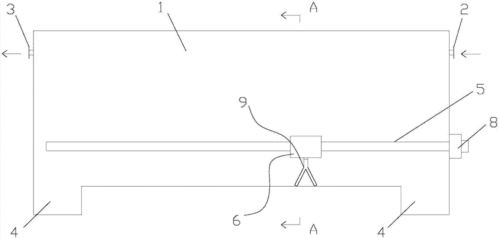
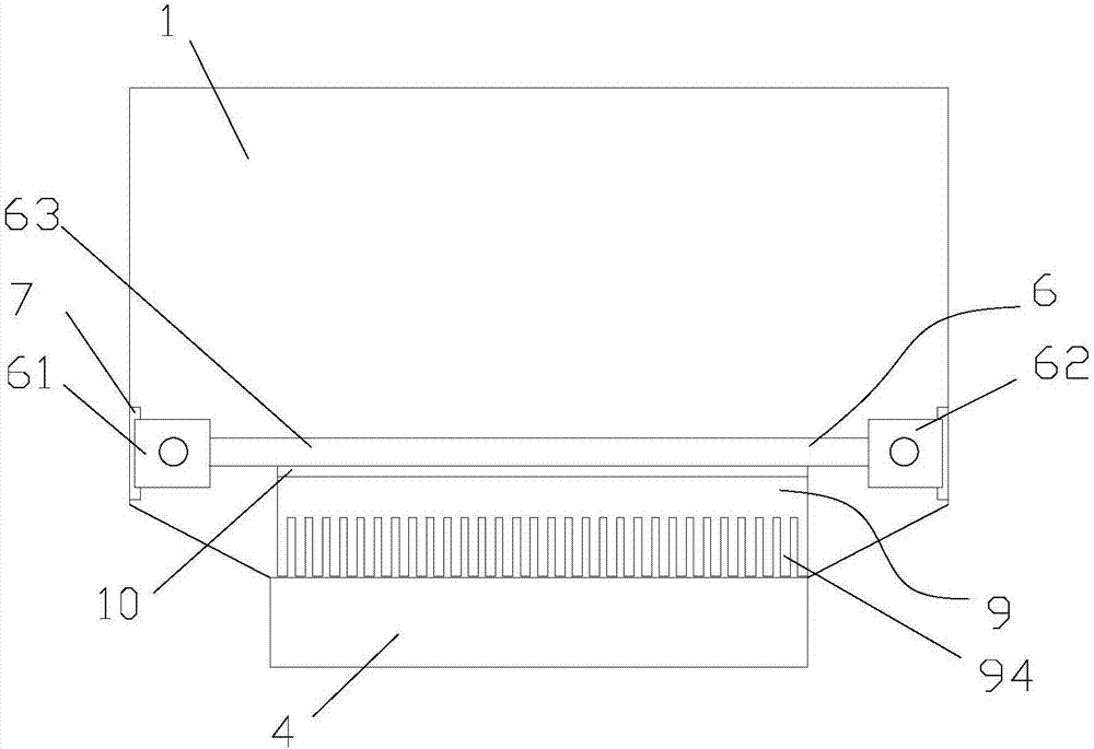
[0026] Such as figure 1 , 2 , 3, a kind of closed aerated grit chamber provided by the present invention comprises grit chamber 1, sand scraping mechanism; Said grit chamber 1 is a closed box structure, one end is provided with water inlet 2, and the other end is provided with There is a water outlet 3; both ends of the bottom of the grit chamber 1 are provided with sand collecting parts 4. The top of the grit chamber 1 is fully sealed to reduce the leakage of odor.

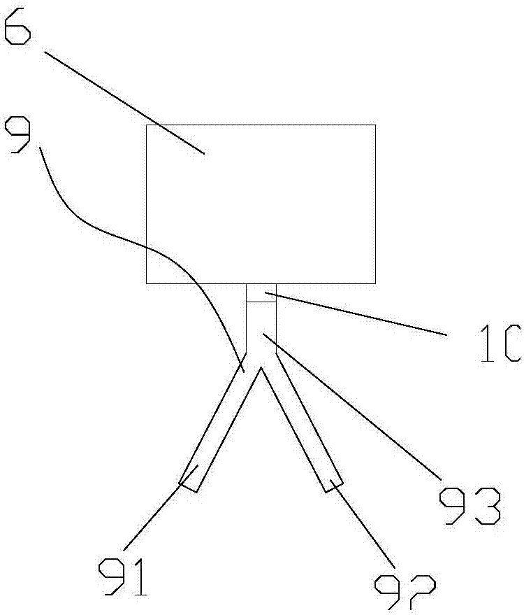
[0027] The sand scraping mechanism is arranged at the bottom of the grit chamber 1, and the sand scraping mechanism includes a rotating part 5 extending along the length direction of the grit chamber 1, a moving part 6 and a scraper 9 arranged on the rotating part 5; The rotation of the part 5 can drive the moving part 6 to move in the length direction of the grit chamber 1; the scraper 9 is installed on the moving part 6 and moves together with the moving part 6 to scrape the sand at the bottom of the grit cha...


PUM

PropertyMeasurementUnit
widthaaaaaaaaaa

Abstract

A sealed aerated grit chamber comprises a grit chamber body and a grit scraping mechanism, wherein the grit chamber body adopts a sealed box structure, a water inlet is formed in one end of the grit chamber body, a water outlet is formed in the other end of the grit chamber body, and grit collection parts are arranged at two ends of the bottom of the grit chamber body; the grit scraping mechanism is arranged at the bottom of the grit chamber body and comprises a rotary part, a moving part arranged at the rotary part and a scraping plate, the rotary part rotates to drive the moving part to move in the length direction of the grit chamber body, the scraping plate is mounted at the moving part and moves along with the moving part to scrape grit at the bottom of the grit chamber body to the grit collection part, and grit in the grit collection part 4 is discharged out together. Accordingly, grit depositing and discharging treatment integrated design is realized, and the grit removal efficiency is high; the top of the grit chamber body can be fully sealed, and leaking of odor is reduced. Meanwhile, the upper space of the top of the grit chamber body is saved due to the fact that no other equipment is mounted at the top of the grit chamber body, grit at the bottom of the grit chamber body can be removed effectively, and no blind area of grit scraping exists.

Description

technical field [0001] The invention relates to the field of sewage treatment, in particular to a closed aeration grit chamber. Background technique [0002] In recent years, due to the improvement of environmental protection standards on the effluent indicators of sewage plants, and some of the sewage needs to be regenerated and reused after treatment, it is difficult to meet the current effluent requirements by relying on the simple biological treatment process in the past, especially in the influent water of sewage plants. If it enters the biological reaction system, it will be detrimental to the system. Therefore, the gravel should be removed at the source of the sewage treatment plant to reduce operating costs and energy consumption. [0003] At present, the advection type aeration grit chamber sand removal equipment used in municipal sewage plants generally adopts the traditional bridge-type sand suction machine fixed on the top of the sewage treatment tank, which uses...

Claims


Application Information

Patent Timeline
Patent Type & Authority Applications(China)
IPC IPC(8): B01D21/06B01D21/24
CPCB01D21/06B01D21/245
Inventor 张艳玲邓梁
Owner 湖南美奕机电科技有限公司
Why Eureka
Try Eureka