Wire clamp mechanism

A wire clip and wire clip body technology, applied in the direction of transformer/inductor coil/winding/connection, etc., can solve the problems of low reliability and achieve good airtightness

Active Publication Date: 2019-09-10
STATE GRID BEIJING ELECTRIC POWER +1
View PDF13 Cites 0 Cited by
  • Summary
  • Abstract
  • Description
  • Claims
  • Application Information

AI Technical Summary

Problems solved by technology

[0005] The main purpose of the present invention is to provide a wire clamp mechanism to solve the problem of low reliability in the prior art of using the sheath of insulated wires to wrap the bare point of the bus bar of the transformer

Method used


Image

  • Wire clamp mechanism
  • Wire clamp mechanism
  • Wire clamp mechanism

Examples


Embodiment Construction

[0032] It should be noted that, in the case of no conflict, the embodiments in the present application and the features in the embodiments can be combined with each other. The present invention will be described in detail below with reference to the accompanying drawings and examples.

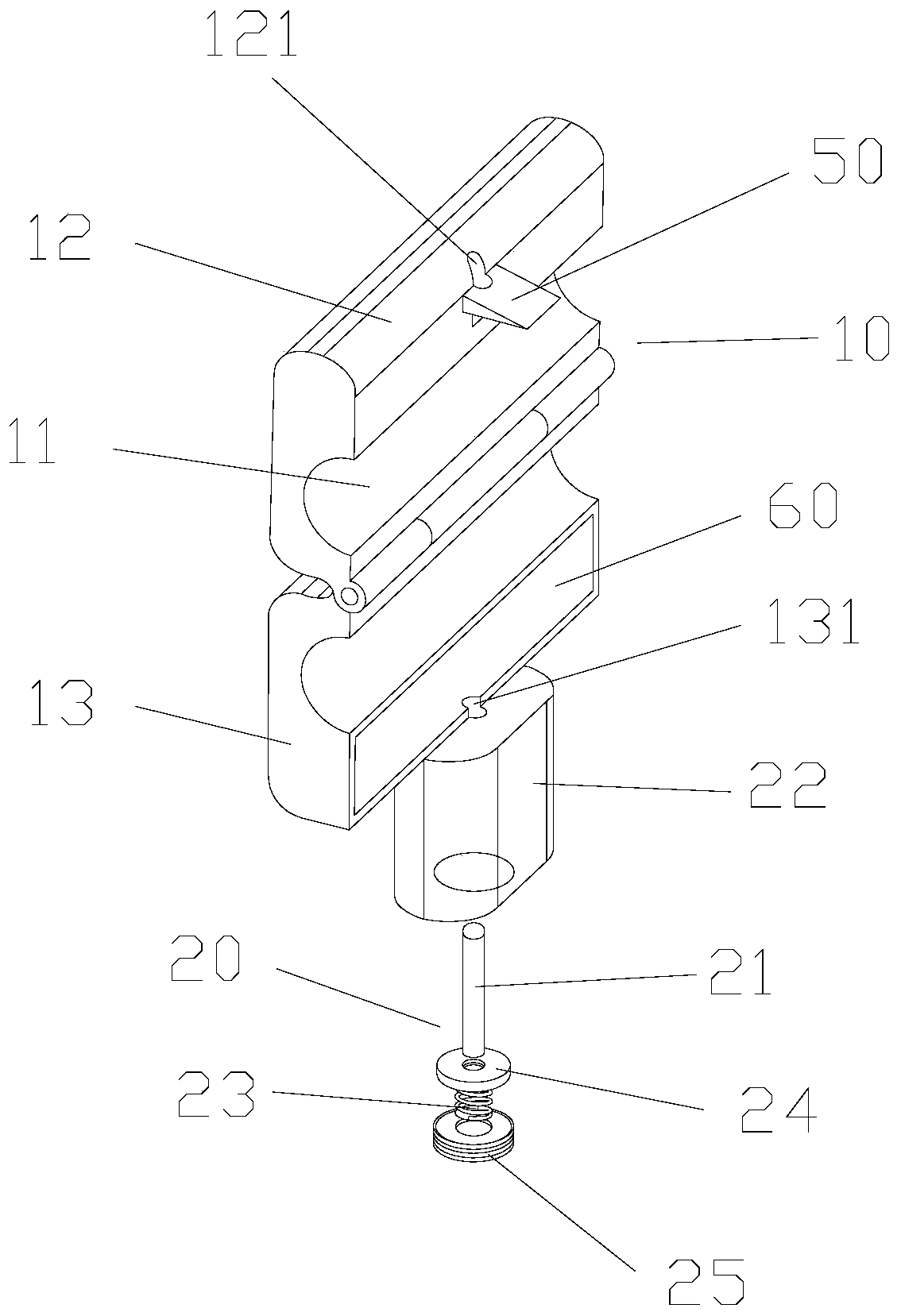
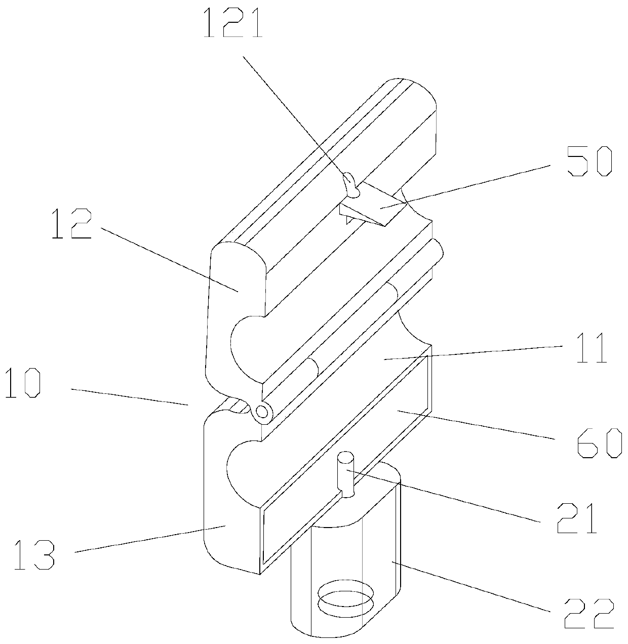
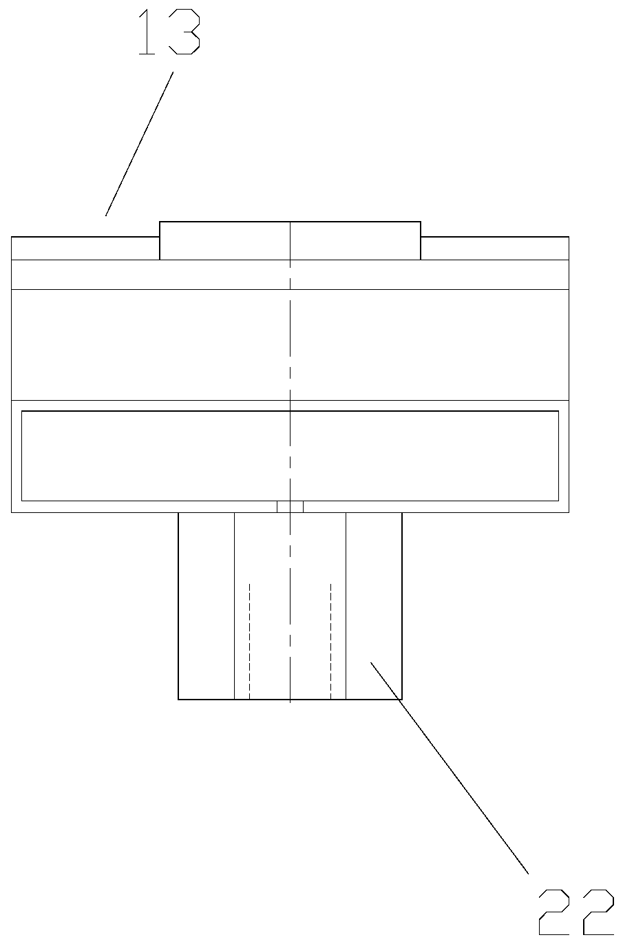
[0033] The present invention provides a wire clip mechanism, please refer to Figure 1 to Figure 8 , the wire clamp mechanism includes: a wire clamp body 10, the wire clamp body 10 has an accommodating cavity 11 for accommodating the wire body; The clip body 13 , the first clip body 12 is adjustable relative to the second clip body 13 to open or close the accommodating cavity 11 , so that the clip body 10 wraps around the cable body. Wherein, the first clamp body 12 is provided with a first groove, and the second clamp body 13 is provided with a second groove, and the first groove and the second groove are spliced ​​to form the accommodating cavity 11 . It can be seen that when the first wire...


PUM


Abstract

The invention provides a wire clamp mechanism, which comprises a wire clamp body, wherein the wire clamp body is provided with an accommodating cavity for accommodating a wire body; the wire clamp body comprises a first wire clamp body and a second wire clamp body for enclosing the accommodating cavity; and the first wire clamp body is adjustably arranged relative to the position of the second wire clamp body to open or close the accommodating cavity, thereby coating the wire body with the wire clamp body. According to the wire clamp mechanism, the problem of relatively low reliability of a mode of wrapping an exposed point of a bus of a transformer with a wire sheath of an insulated wire in the prior art is solved.

Description

technical field [0001] The invention relates to the field of electric power, in particular to a wire clamp mechanism. Background technique [0002] The primary line of the mother-type transformer operating on the 10kV power line is an insulated wind and rain line. In order to ensure the safety of construction personnel during maintenance, protective grounding must be carried out on the primary side of the transformer. Therefore, a maintenance grounding port is reserved on the primary bus of the transformer. Here The wire insulation of the line is stripped and becomes a bare point in the operation of the line. [0003] In the line operation, although the maintenance grounding port of the mother-type substation can be conveniently sealed and hung in the line maintenance to provide grounding protection for the construction personnel, but in daily operation, this place has become a weak point in the operation of the power grid , because its insulation is damaged, in bad weather...

Claims


Application Information

Patent Timeline
Patent Type & Authority Patents(China)
IPC IPC(8): H01F27/32H01F27/29
Inventor 任立新李枫辉王岩
Owner STATE GRID BEIJING ELECTRIC POWER
Why Eureka
Try Eureka