Charging method, device, charger, terminal and system

A charging method and charger technology, applied in circuit devices, battery circuit devices, charging/discharging current/voltage regulation, etc., can solve problems such as affecting charger identification and affecting signal quality.

Active Publication Date: 2017-09-01
BEIJING XIAOMI MOBILE SOFTWARE CO LTD
View PDF3 Cites 7 Cited by
  • Summary
  • Abstract
  • Description
  • Claims
  • Application Information

AI Technical Summary

Problems solved by technology

On the one hand, the above connection method will affect the identification of the charger, and there is a hidden danger of incorrect identification of the charger. On the other hand, it will also affect the signal quality during data transmission between the USB master and slave devices.

Method used


Image

  • Charging method, device, charger, terminal and system
  • Charging method, device, charger, terminal and system
  • Charging method, device, charger, terminal and system

Examples


Embodiment Construction

[0128] Reference will now be made in detail to the exemplary embodiments, examples of which are illustrated in the accompanying drawings. When the following description refers to the accompanying drawings, the same numerals in different drawings refer to the same or similar elements unless otherwise indicated. The implementations described in the following exemplary examples do not represent all implementations consistent with the present disclosure. Rather, they are merely examples of apparatuses and methods consistent with aspects of the present disclosure as recited in the appended claims.

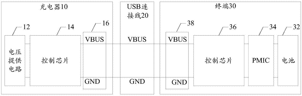
[0129] Figure 1A It is a schematic diagram of a charging system shown according to an exemplary embodiment. Such as Figure 1A As shown, the charging system includes: a charger 10 , a USB connection line 20 and a terminal 30 . Wherein, the charger 10 is connected to the terminal 30 through the USB connection line 20 .

[0130] The charger 10 is also called a power adapter, and is us...


PUM


Abstract

The invention relates to a charging method, a device, a charger, a terminal and a system, belonging to the technical field of power supply. The method comprises the following steps: a charger sends the configuration information thereof to a terminal through a VBUS pin; the charger receives output indication information from the terminal through the VBUS pin, wherein the output indication information is determined by the terminal according to the configuration information and the current state parameters of the battery of the terminal; and a voltage supply circuit and the VBUS pin are connected, and the voltage supply circuit outputs electric energy for charging the battery of the terminal to the terminal under control according to the output indication information. A charger is identified through the VBUS pin, and data is transmitted through a DP pin and a DM pin. Bifurcation of the transmission path of a data line connected with the DP pin and the DM pin is avoided fundamentally. The success rate of charger identification is improved. The quality of signals in data transmission between USB master and slave equipment is ensured.

Description

technical field [0001] The present disclosure relates to the technical field of power supply, and in particular to a charging method, device, charger, terminal and system. Background technique [0002] Currently, terminals such as mobile phones and tablet computers usually use USB (Universal Serial Bus, Universal Serial Bus) interfaces for charging and data transmission. [0003] The USB interface includes VBUS (voltage bus) pins, DP (Digital Positive, data positive) pins (also called D+ pins), DM (Digital Minus, data negative) pins (also called D- pins) and GND (Ground, ground) pin. In related technologies, the DP pin and the DM pin are respectively electrically connected to the charging IC (Integrated Circuit, integrated circuit) built in the terminal. When the terminal is connected to the charger through the USB interface, the charging IC is The DM pin communicates with the charger to realize the identification of the charger. In addition, the DP pin and the DM pin are...

Claims


Application Information

Patent Timeline
Patent Type & Authority Applications(China)
IPC IPC(8): H02J7/00
CPCH02J7/007
Inventor 解霏郝宁赵青晖
Owner BEIJING XIAOMI MOBILE SOFTWARE CO LTD
Why Eureka
Try Eureka