System for assisting head precision surgery positioning
A precise and surgical technology, applied in the medical field, can solve the problems of inconvenient operation, displacement of the stereotaxic frame, large labor cost investment, etc.
- Summary
- Abstract
- Description
- Claims
- Application Information
AI Technical Summary
Problems solved by technology
Method used
Image
Examples
Embodiment 1
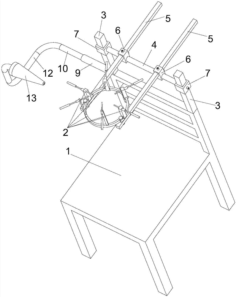
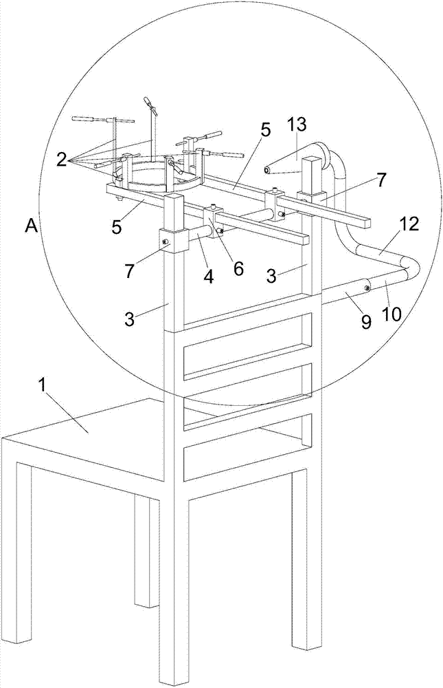
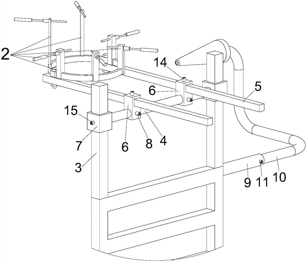
[0033] In this example, if Figure 1 to Figure 7 As shown, a system for assisting precise surgical positioning of the head includes a seat 1, a stereotaxic frame 2, a connection support frame, a projector support and a scan map projector 13, and the above connection support frame and the projector support are installed on On the above-mentioned seat 1, the above-mentioned stereotactic frame 2 is detachably mounted on the above-mentioned connecting support frame, and the above-mentioned scanning image projector 13 is detachably mounted on the above-mentioned projector bracket. Specifically, it is defined that the above-mentioned seat 1 includes a bench and a backrest, the above-mentioned connecting support frame is installed on the top wall of the above-mentioned backrest, and the above-mentioned projector bracket is installed on the right side wall of the above-mentioned backrest. In this embodiment, the scan chart projector 13 can project a scan chart of the patient's head. T...
Embodiment 2
[0042] This embodiment is further limited on the basis of Embodiment 1. In this embodiment, the above-mentioned horizontal through hole is defined as a round hole, and the above-mentioned elevating cross bar 4 is defined as a round rod. When it is in the hole, the connecting base 6 can rotate relative to the lifting cross bar 4, so that the above-mentioned telescopic support rod 5 can roll over relative to the above-mentioned lifting cross bar 4. When the present invention is not needed, the above-mentioned telescopic support rod 5 can be rolled to a vertical state, and when it is needed to be used, the above-mentioned telescopic support rod 5 can be rolled to a horizontal state. The end of 5 is detachably mounted on the above-mentioned stereotaxic frame 2. With this structure, when the above-mentioned telescopic support rod 5 is in a vertical state, the volume space occupied by it is smaller, which is convenient for storage and transportation.
Embodiment 3
[0044] This embodiment is further limited on the basis of Embodiment 1. In this embodiment, the first locking structure 15, the second locking structure 8, the third locking structure 14 and the fourth locking structure 11 are defined as A screw compression pair, the screw compression pair includes a threaded hole and a compression screw screwed in the threaded hole. Specifically, the threaded holes are respectively provided on the wall of the outer tube 9, the wall of the transverse through hole, the wall of the longitudinal through hole and the wall of the vertical through hole, and a compression screw is also included, and the compression screw is screwed on the In the threaded hole, when the compression screw is tightened in the threaded hole, the top of the above-mentioned compression screw will be compressed on the outer wall of the inner tube 10 or the outer wall of the lifting cross bar 4 or the outer wall of the telescopic support rod 5 or the outer wall of the column ...
PUM
 Abstract
Description
Claims
Application Information
 - R&D
- Intellectual Property
- Life Sciences
- Materials
- Tech Scout
- Unparalleled Data Quality
- Higher Quality Content
- 60% Fewer Hallucinations
Browse by: Latest US Patents, China's latest patents, Technical Efficacy Thesaurus, Application Domain, Technology Topic, Popular Technical Reports.
© 2025 PatSnap. All rights reserved.Legal|Privacy policy|Modern Slavery Act Transparency Statement|Sitemap|About US| Contact US: help@patsnap.com


