Laser cutting device for cloth

A laser cutting and fabric technology, applied in laser welding equipment, welding equipment, metal processing equipment, etc., can solve problems such as affecting the working efficiency of fabric cutting operations, poor surface tension performance of fabrics, easy to sag or wrinkle, etc., to reduce labor costs. The effect of labor intensity, high cutting precision and high degree of automation

Inactive Publication Date: 2017-09-05
PINGHU XING TIANYOUNG CLOTHING TECH CO LTD
View PDF12 Cites 17 Cited by
  • Summary
  • Abstract
  • Description
  • Claims
  • Application Information

AI Technical Summary

Problems solved by technology

[0002] At present, in the processing industry that uses cloth as raw material for products, it is necessary to cut a large amount of cloth according to the needs of use. At present, in order to improve the quality and work efficiency of the cloth cutting operation, it is mainly through special cloth laser cutting. equipment, but in actual use, it is found that there is often a large conveying distance between the upper cloth roller and the laser cutting device of the currently used laser cutting cloth, and the conveying distance is fixed, so when cutting the cloth, the cloth It is difficult to load the material, and in the cutting process, it is easy to cause the cloth to fall off, which seriously affects the work efficiency of the cloth cutting operation. At the same time, due to the large conveying distance, the surface tension of the cloth is extremely poor. It is easy to sag or wrinkle, which seriously affects the cutting quality of the cloth. Therefore, in view of this situation, it is urgent to develop a new type of cloth laser cutting device to meet the needs of actual use.
[0003] Chinese patent publication number 204893220U provides a new type of cloth laser cutting machine, including a frame, a driving mechanism, a guide rail, an upper cloth roller, an adjustment mechanism, a cutting shaft and a laser cutting device, wherein the cutting shaft is installed through a support arm At the discharge port of the frame, the cutting shaft is distributed parallel to the upper surface of the frame, the laser cutting device is slidingly connected with the cutting shaft, and at least one guide rail is installed on the frame, and the guide rail is connected to the machine frame. The moving direction of the frame cloth is distributed in parallel, and an upper cloth slider and at least one adjustment slider are arranged on the guide rail, wherein the upper cloth slider is located at the feeding port of the rack, and the adjusting slider is located at the outlet of the rack. The position between the opening and the feeding port, and the upper cloth slider and the adjustment slider are slidingly connected to the guide rail through the sliding drive mechanism, and the upper cloth roller is connected to the upper cloth slider through the support arm. The adjustment mechanism is installed on the adjustment slider and is located between the upper cloth roller and the cutting shaft. The adjustment mechanism includes a tension adjustment drive mechanism, an adjustment arm, an adjustment roller and a tension sensor, wherein the adjustment arm The end is hinged with the adjustment slider, the front end is connected with the adjustment roller, the end of the adjustment arm is also connected with the tension adjustment drive mechanism, the tension sensor is installed on the roller shaft of the adjustment roller, and is electrically connected with the tension adjustment drive mechanism, The driving mechanism is installed on the frame, and is respectively connected with the upper cloth roller and the adjustment roller of the adjustment mechanism; the defect of the laser cutting machine with this structure is that when the laser cutting machine cuts the cloth, the cloth is very easy to move, and at the same time , The reliability or stability of the cutting machine during the movement is insufficient, the function is single, and the efficiency is not high, which will cause errors in the flatness of the fabric and cutting

Method used


Image

  • Laser cutting device for cloth
  • Laser cutting device for cloth
  • Laser cutting device for cloth

Examples


Embodiment

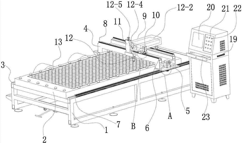
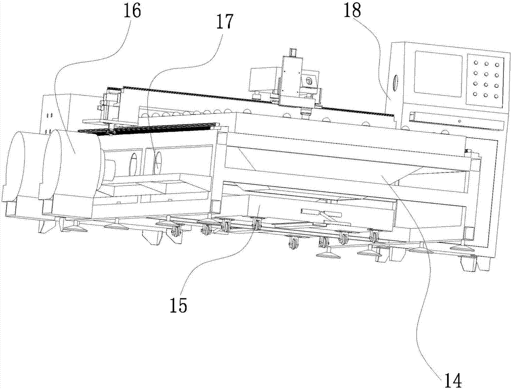
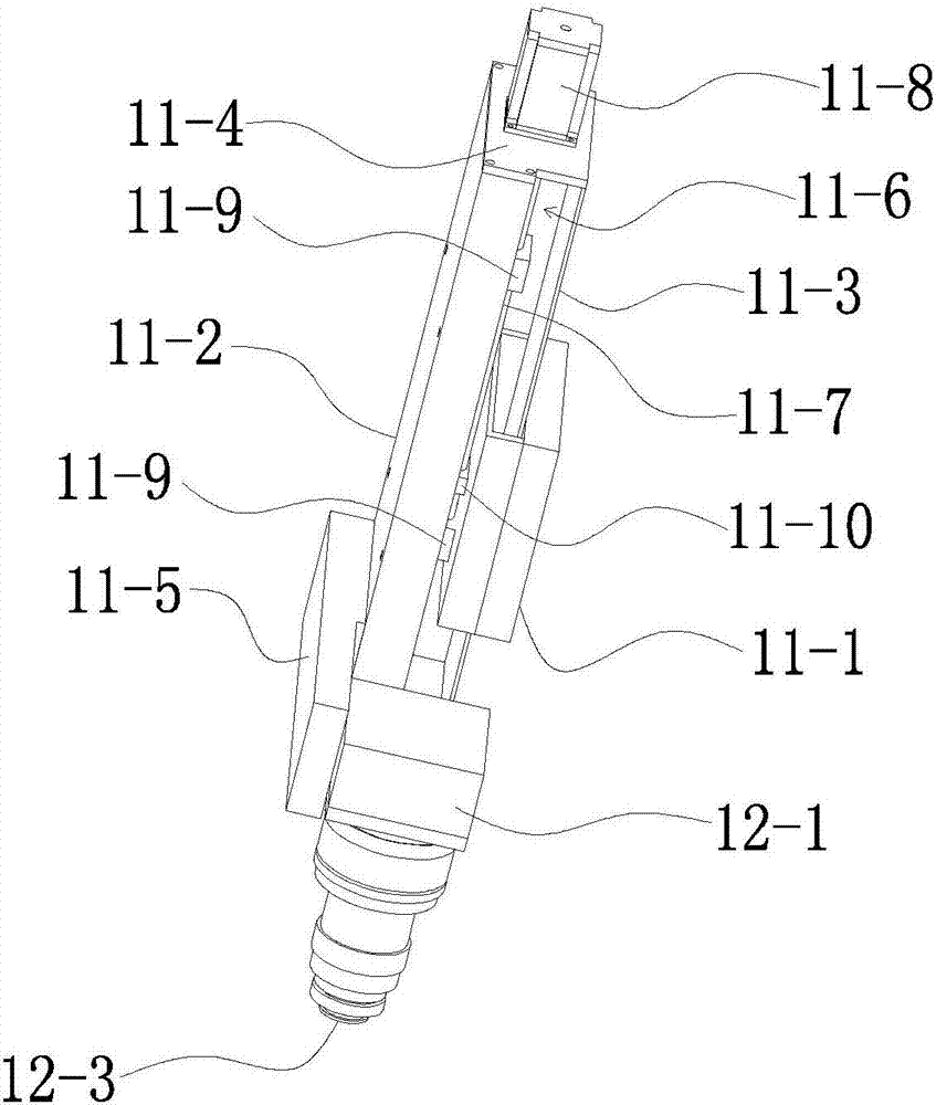
[0031] Example: such as Figure 1-5As shown, a laser cutting device for cloth includes a base 1, a working platform 2 and a beam 4; the working platform 2 is arranged on the base 1; A linear guide rail 3, two first slideways 7 are fixed on the two first linear guide rails 3; the two first linear guide rails 3 are located on both sides of the working platform 2; the two ends of the beam 4 are respectively Slidingly connected to two first slideways 7; the two ends of the crossbeam 4 are provided with a first driving device 5 for driving the crossbeam 4 to move along the length direction of the two first slideways 7; the crossbeam 4 is provided with Two second linear guide rails 6 arranged along the length direction of the beam 4, two second linear guide rails 6 are fixedly provided with two second slideways 8; the two second slideways 8 are provided with square boxes 9. The square box 9 and the two second slideways 8 are perpendicular to each other, and one side of the square b...


PUM


Abstract

The invention relates to a perforating device for cloth. A laser cutting device for the cloth comprises a base, a working platform and a cross beam; two first linear guide rails arranged in the length direction of the base are arranged on the base; two first slides are fixedly arranged on the two first linear guide rails; two ends of the cross beam are glidingly connected onto the two first slides; first driving devices for driving the cross beam to move in the length direction of the two first slides are arranged at the two ends of the cross beam; two second linear guide rails arranged in the length direction of the cross beam are arranged on the cross beam; two second slides are fixedly arranged on the two second linear guide rails; a square box is arranged on the two second slides; the front end of the square box is glidingly connected with a moving seat device; and a laser cutting mechanism is arranged on the moving seat device and is corresponding to the position of the working platform. The laser cutting device is simple in structure, convenient and quick to use, high in automation degree and capable of realizing quick feeding of a laser cutting head and improving the production efficiency.

Description

technical field [0001] The invention belongs to the technical field of cloth production equipment, and in particular relates to a laser cutting device for cloth. Background technique [0002] At present, in the processing industry that uses cloth as raw material for products, it is necessary to cut a large amount of cloth according to the needs of use. At present, in order to improve the quality and work efficiency of the cloth cutting operation, it is mainly through special cloth laser cutting. equipment, but in actual use, it is found that there is often a large conveying distance between the upper cloth roller and the laser cutting device of the currently used laser cutting cloth, and the conveying distance is fixed, so when cutting the cloth, the cloth It is difficult to load the material, and in the cutting process, it is easy to cause the cloth to fall off, which seriously affects the work efficiency of the cloth cutting operation. At the same time, due to the large co...

Claims


Application Information

Patent Timeline
Patent Type & Authority Applications(China)
IPC IPC(8): B23K26/06B23K26/38B23K26/40B23K26/70
CPCB23K26/38B23K26/0643B23K26/40B23K26/702
Inventor 颜泽君
Owner PINGHU XING TIANYOUNG CLOTHING TECH CO LTD
Why Eureka
Try Eureka