Wind tunnel test device of windscreen wiper pressing force distribution and windscreen wiper controlling method

A test device and technology of wiper, which is applied in the direction of measurement device, machine/structural component test, fluid pressure measurement by changing ohmic resistance, etc. It can solve problems such as detachment, impact on vehicle safety, and different pressing force of wiper, etc., to achieve Avoid water waste, strong rigidity, and small flow field disturbance

Pending Publication Date: 2017-09-05
JILIN UNIV
View PDF8 Cites 12 Cited by
  • Summary
  • Abstract
  • Description
  • Claims
  • Application Information

AI Technical Summary

Problems solved by technology

Due to wind interference, the pressing force of the wiper is different at different speeds of the vehicle, and may even rise and break away from the surface of the window glass, affecting the safety of the vehicle at high speed
Therefore, wind tunnel experiments are required to test the compressive force performance of the wiper at high vehicle speeds during the design of the wiper. The current measuring device for the compressive force of the wiper is limited to static measurement, and cannot accurately measure the pressure distribution and the compressive force of the scraping area. Variations with vehicle speed

Method used


Image

  • Wind tunnel test device of windscreen wiper pressing force distribution and windscreen wiper controlling method
  • Wind tunnel test device of windscreen wiper pressing force distribution and windscreen wiper controlling method
  • Wind tunnel test device of windscreen wiper pressing force distribution and windscreen wiper controlling method

Examples


Embodiment Construction

[0047] The present invention will be further described in detail below with reference to the accompanying drawings, so that those skilled in the art can implement it with reference to the text of the description.

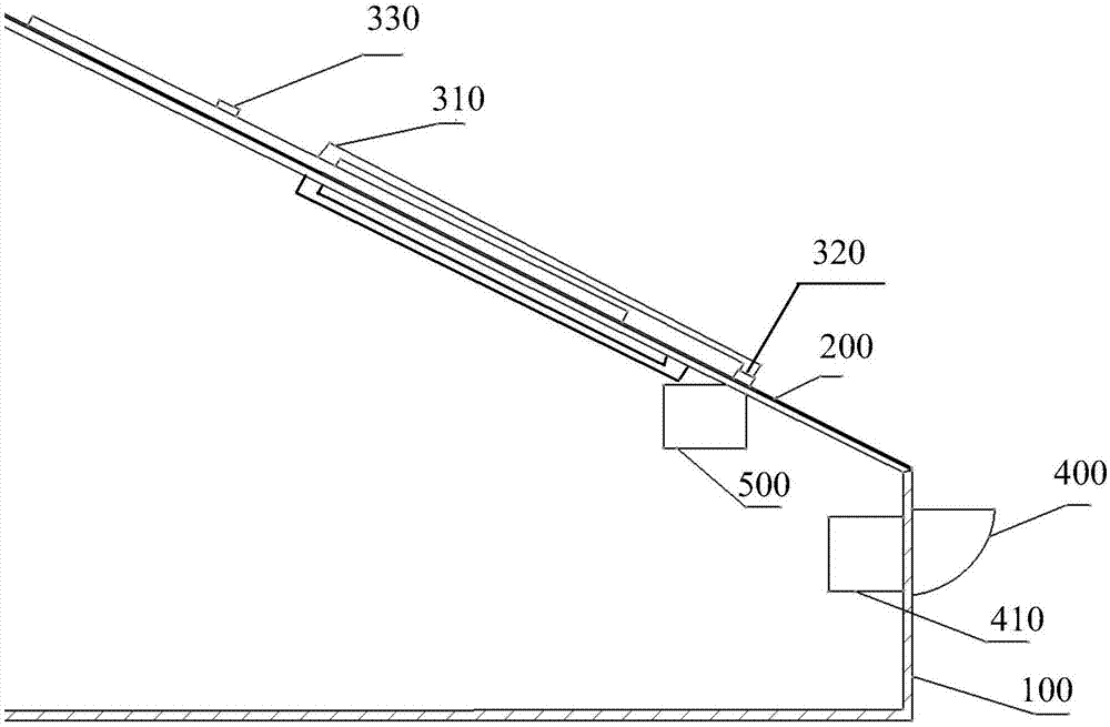
[0048] Such as figure 1 As shown, the wind tunnel test device for wiper compression force distribution provided by the present invention includes: a support frame 100, a laminated glass 200, a wiper 300 and a water tank 400.

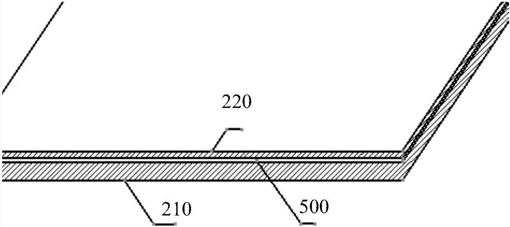
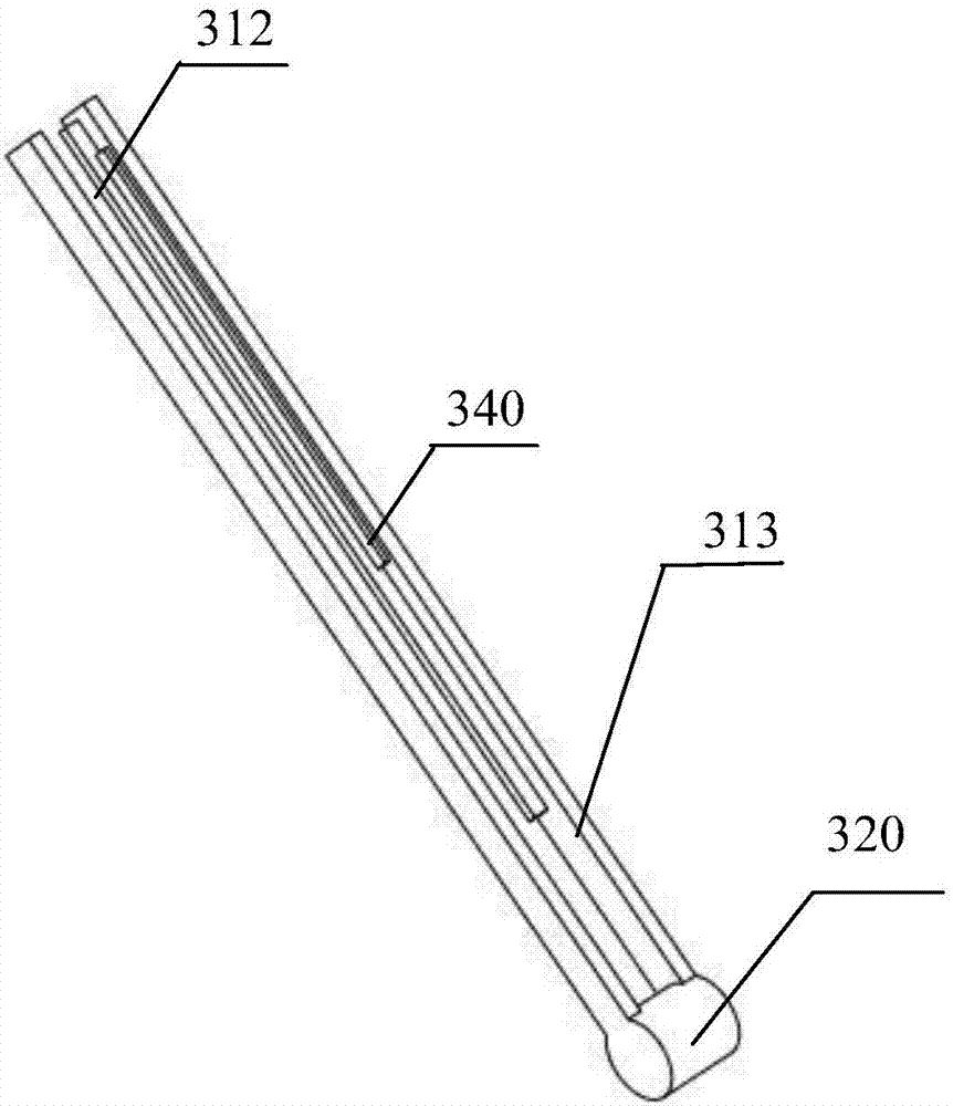
[0049] Wherein, the top of the support frame 100 is provided with a laminated glass 200, which includes an outer glass layer 210 and an inner glass 220; the wiper blade 300 is arranged on the outside of the laminated glass 200, including a wiper arm 310 which is attached to the outer glass layer The surface; the rotating shaft 320, which is set at one end of the wiper arm 310, the wiper arm 310 can rotate around the rotating shaft 320; the water spray port 330, which is set on the other end of the wiper arm 310; the water tank 400, which is set at ...


PUM

PropertyMeasurementUnit
thicknessaaaaaaaaaa

Abstract

The invention discloses a wind tunnel test device of windscreen wiper pressing force distribution. The device comprises a supporting frame, laminated glass, a windscreen wiper, a rotary shaft, a water spraying nozzle, a water tank and a sensor array, wherein the laminated glass comprises an outer glass thin layer and an inner glass layer; the windscreen wiper is arranged on the outer side of the laminated glass and comprises a windscreen wiper arm, and the windscreen wiper arm is arranged on the surface of the outer glass thin layer in an attached mode; the rotary shaft is arranged at one end of the windscreen wiper arm, and the windscreen wiper arm can rotate around the rotary shaft; the water spraying nozzle is arranged at the other end of the windscreen wiper arm; the water tank is arranged at the lower end of the device and connected with the water spraying nozzle through a water pump; the sensor array is arranged between the outer glass thin layer and the inner glass layer. The technical purpose is to provide a wind tunnel test device of windscreen wiper pressing force distribution. According to the pressure of different scraping areas, the state of the windscreen wiper pressing force distribution and the change rule of windscreen wiper pressing force with wind speed are obtained, and a reference is provided for design and improvement of the windscreen wiper; a windscreen wiper controlling method is also provided, the change rule of the windscreen wiper pressing force with vehicle speed is measured based on the wind tunnel test of the windscreen wiper, and the pressing force of the windscreen wiper arm is adjusted through the magnitude of a current, so that a better scraping effect is obtained.

Description

Technical field [0001] The invention relates to the field of automobiles, in particular to a wind tunnel test device for the pressure distribution of a wiper wiper and a wiper control method. Background technique [0002] The pressing force of the wiper when the vehicle is traveling at different speeds is an important performance index to measure the wiper. Due to the interference of wind, the pressing force of the wiper at different vehicle speeds is different, and it may even rise and separate from the surface of the window glass, which affects the safety of the vehicle at high speed. Therefore, when designing the wiper, it is necessary to conduct a wind tunnel test on the pressing force performance of the wiper at high speeds. The current wiper pressing force measurement device is limited to static measurement and cannot accurately test the pressure distribution and pressing force of the wiper area. Changes with the speed of the vehicle. Summary of the invention [0003] The ...

Claims


Application Information

Patent Timeline
Patent Type & Authority Applications(China)
IPC IPC(8): G01L9/02G01M9/06B60S1/08
CPCG01L9/02G01M9/06B60S1/0818
Inventor 胡兴军惠政郭鹏辛俐张靖龙王靖宇孙兴智丁九洋黄珊刘龙威齐胜业王坤阳乔银波董春波曹庆炜
Owner JILIN UNIV
Why Eureka
Try Eureka