
Isolation material, method for preparing same, display panel and display device

A technology for display panels and spacers, applied in nonlinear optics, instruments, optics, etc., can solve the problems of poolingmura light leakage, large spacer compression, etc., to improve supporting force, small compression, and solve light leakage. effect of the phenomenon

Inactive Publication Date: 2017-09-05
BOE TECH GRP CO LTD
View PDF11 Cites 0 Cited by
  • Summary
  • Abstract
  • Description
  • Claims
  • Application Information

AI Technical Summary

Problems solved by technology

[0004] The present invention provides a spacer, a method for preparing the spacer, a display panel and a display device, so as to solve the problems in the prior art that the spacer is compressed by a large amount of force, and liquid crystal diffuses to the surroundings to cause light leakage in the pooling mura

Method used


Image

  • Isolation material, method for preparing same, display panel and display device
  • Isolation material, method for preparing same, display panel and display device
  • Isolation material, method for preparing same, display panel and display device

Examples


Embodiment 1

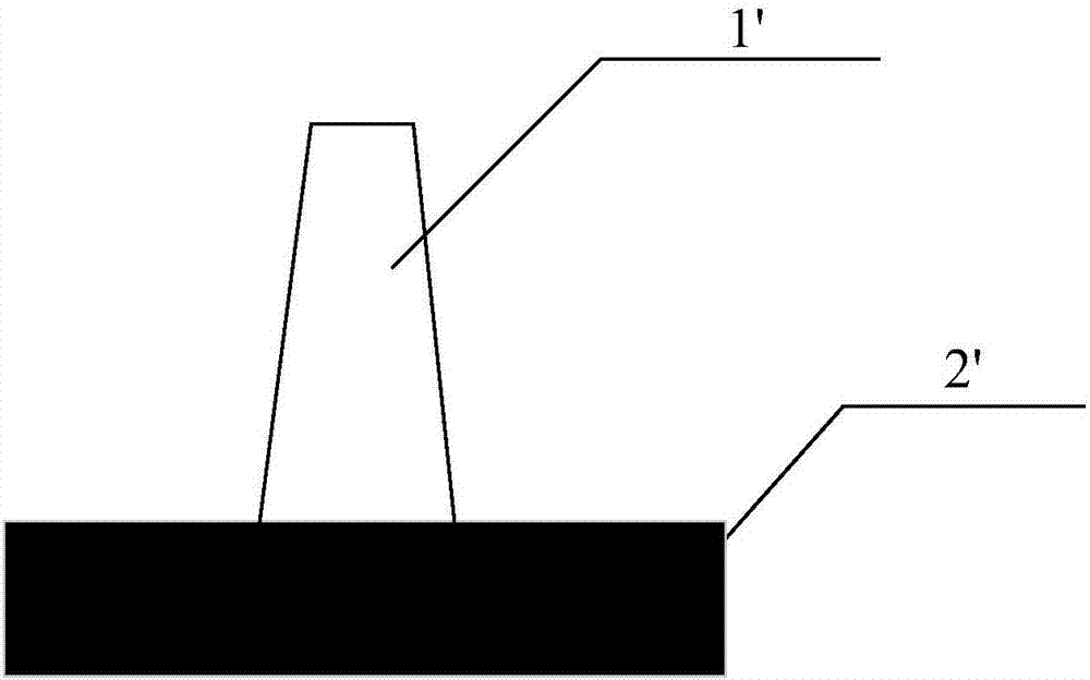
[0035] refer to Figure 4 , is a structural schematic diagram of a spacer according to an embodiment of the present invention.

[0036] The spacer is disposed between the first substrate and the second substrate of the display panel, and is formed on the black matrix 2 of the first substrate. The spacer includes a first component 101 and a second component 102 .

[0037] The first part 101 is formed on the black matrix 2, the first part 101 has two opposite first end faces and second end faces, and the first end face of the first part 101 is bonded to the black matrix 2, the first part 101 of the first part 101 The area boundary of one end surface coincides with the area boundary of the black matrix 2 where it is bonded, and the area of ​​the second end surface of the first component 101 is not larger than the area of ​​the first end surface;

[0038] The second part 102 is formed on the second end face of the first part 101, the second part 102 has a third end face and a fou...

Embodiment 2

[0047] refer to Figure 7 , is a flowchart of a method for preparing a spacer according to an embodiment of the present invention.

[0048] Step 1, forming the first part of the spacer on the black matrix of the first substrate through the first patterning process.

[0049] The first component has opposite first end surfaces and second end surfaces, and the first end surfaces of the first components are bonded to the black matrix.

[0050] Specifically include the following processes:

[0051] forming a photoresist layer for making the first component on the black matrix of the first substrate;

[0052] The photoresist layer is exposed and developed by using the first mask to form the first component on the black matrix of the first substrate, wherein the first mask is a mask for making the black matrix on the first substrate.

[0053] In this way, the mask plate of the black matrix is ​​used to expose and develop the photoresist layer of the first part to make the first pa...


PUM


Abstract

The invention discloses an isolation material, a method for preparing the same, a display panel and a display device. The isolation material comprises a first component and a second component. The first component is formed on a black matrix and is provided with a first end surface and a second end surface which are opposite to each other, the first end surface of the first component clings to the black matrix, region boundaries of the first end surface coincide with region boundaries of first end surface clinging locations of the black matrix, and the area of the second end surface is not larger than that of the first end surface; the second component is formed on the second end surface of the first component and is provided with a third end surface and a fourth end surface which are opposite to each other, the third end surface clings to the second end surface, region boundaries of the third end surface do not exceed region boundaries of the second end surface, and the area of the fourth end surface is smaller than that of the third end surface.

Description

technical field [0001] The invention relates to the technical field of displays, in particular to a spacer, a preparation method of the spacer, a display panel and a display device. Background technique [0002] The liquid crystal display panel is an important part of the liquid crystal display device. In the liquid crystal display panel, spacers (Support Pillars, PS) are mainly used to maintain the cell thickness of the upper and lower substrates of the display panel, so as to ensure the space for liquid crystal injection. [0003] When the liquid crystal display panel is subjected to an external force, due to the large compression of the spacer, the liquid crystal cell is squeezed and deformed, causing the liquid crystal to diffuse to the surroundings, resulting in a phenomenon of water ripples (pooling mura) in the liquid crystal display device. refer to figure 1 , figure 2 and image 3 , figure 1 It is a structural schematic diagram of a spacer in the prior art, f...

Claims


Application Information

Patent Timeline
Patent Type & Authority Applications(China)
IPC IPC(8): G02F1/1339
CPCG02F1/13394G02F1/13398
Inventor 王新星姚继开柳在健
Owner BOE TECH GRP CO LTD
Learn More