
Image processing method and device for 3D animation material, equipment and medium

A 3D animation and image processing technology, applied in image data processing, animation production, instruments, etc., to solve problems such as limited simulation effects, inability to build dense mesh vertices, and limited computing performance on mobile terminals.

Active Publication Date: 2017-09-05
厦门黑镜科技有限公司
View PDF5 Cites 2 Cited by
  • Summary
  • Abstract
  • Description
  • Claims
  • Application Information

AI Technical Summary

Problems solved by technology

In computer 3D, due to the high configuration of the computer, the calculation performance is good, and the dense mesh vertices can also be calculated in real time; however, due to hardware limitations on the mobile terminal platform, it is impossible to construct mesh vertices as dense as the computer, so it is generally used. The method of sparse vertices simulates cloth, but the sparser the vertices of the cloth, the more limited the effect of the simulation, especially in collision detection.
[0003] General collision detection techniques have a high probability of passing through colliders in cloth simulations with sparse vertices
However, the computing performance of the mobile terminal is limited, and it is impossible to perform complex collision detection calculations and more vertex simulations.

Method used


Image

  • Image processing method and device for 3D animation material, equipment and medium
  • Image processing method and device for 3D animation material, equipment and medium
  • Image processing method and device for 3D animation material, equipment and medium

Examples


Embodiment Construction

[0026] The application will be further described in detail below in conjunction with the accompanying drawings and embodiments. It should be understood that the specific embodiments described here are only used to explain related inventions, rather than to limit the invention. It should also be noted that, for the convenience of description, only the parts related to the related invention are shown in the drawings.

[0027] It should be noted that, in the case of no conflict, the embodiments in the present application and the features in the embodiments can be combined with each other. The present application will be described in detail below with reference to the accompanying drawings and embodiments.

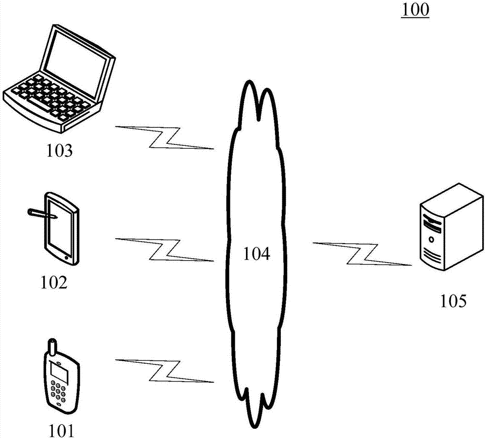
[0028] figure 1 An exemplary system architecture 100 of an embodiment of the method for image processing of 3D animation material or the apparatus for image processing of 3D animation material of the present application can be applied.

[0029] Such as figure 1As shown, th...


PUM


Abstract

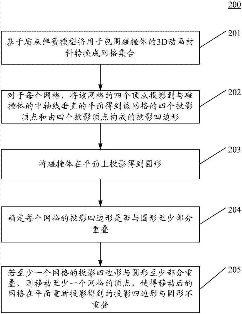
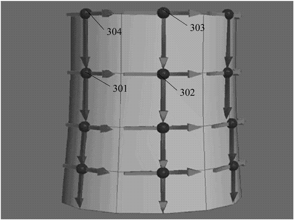
The invention discloses an image processing method and a device for a 3D animation material, equipment and a medium. In one specific embodiment, the method comprises steps: based on a mass spring model, a 3D animation material used to surround a colliding body is converted to a mesh set, wherein the colliding body is converted to a corresponding cylinder structure and each mesh is a quadrilateral formed by four vertices; as for each mesh, the four vertices of the mesh are projected to a plane vertical to the medial axis of the colliding body to obtain four projection vertices of the mesh and a projection quadrilateral formed by the four projection vertices; the colliding body is projected in the plane to obtain a circle; whether the projection quadrilateral of each mesh is at least partially overlapped with the circle is determined; and if the projection quadrilateral of at least one mesh is at least partially overlapped with the circle, vertices of the at least one mesh are moved, and the projection quadrilateral obtained when the mesh after movement is projected again in the plane is not overlapped with the circle. Thus, the image when the 3D animation material passes through the colliding body can be detected and corrected.

Description

technical field [0001] The present application relates to the field of computer technology, specifically to the field of image processing technology, and in particular to a method and device for image processing of 3D animation materials. Background technique [0002] In the current 3D applications, most of the clothing fabrics are simulated based on the particle spring model. On the virtual platform, it is impossible to create very dense vertices like real-world cloth, so the overall structure of the cloth is constructed through the method of grid sampling, and then the patches connected between vertices are rendered. In computer 3D, due to the high configuration of the computer, the calculation performance is good, and the dense mesh vertices can also be calculated in real time; however, due to hardware limitations on the mobile terminal platform, it is impossible to construct mesh vertices as dense as the computer, so it is generally used. The method of sparse vertices s...

Claims


Application Information

Patent Timeline
IPC IPC(8): G06T13/20
CPCG06T13/20
Inventor 方小致
Owner 厦门黑镜科技有限公司
Learn More