Uplink beam tracking method and corresponding terminal and base station

A technology of beam tracking and base station, which is applied in the fields of uplink beam tracking, terminal and base station, which can solve problems such as inability to receive downlink data from the base station, changes in the transmitting and receiving beams, and affecting the communication quality of the terminal, so as to improve user experience, save time delay, The effect of mitigating the impact of business continuity

Active Publication Date: 2017-09-05
ZTE CORP
View PDF4 Cites 22 Cited by
  • Summary
  • Abstract
  • Description
  • Claims
  • Application Information

AI Technical Summary

Problems solved by technology

[0005] However, during the communication process, due to the movement of the terminal, the transmitting and receiving beams will change. In a typical scenario, due to the rotation of the terminal, the preferred uplink transmit beam and the downlink preferred receive beam will change. If the terminal still uses the uplink preferred transmit beam to transmit to the base station The base station will not be able to receive the uplink data sent. Correspondingly, the terminal will not be able to receive the downlink data from the base station through the preferred downlink receiving beam.
If the relevant changes cannot be quickly discovered and a new optimal transceiver beam is identified, service interruption may be caused, which will seriously affect the communication quality of the terminal in high-frequency communication

Method used


Image

  • Uplink beam tracking method and corresponding terminal and base station
  • Uplink beam tracking method and corresponding terminal and base station
  • Uplink beam tracking method and corresponding terminal and base station

Examples


Embodiment 1

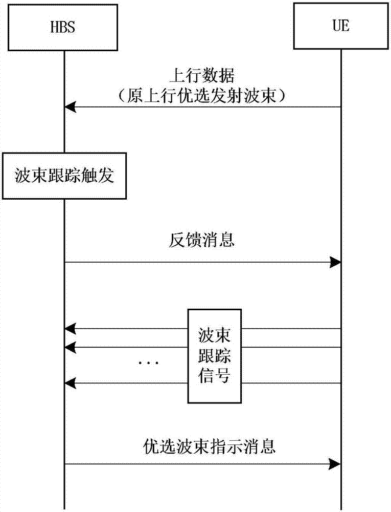
[0063] This embodiment describes the uplink beam tracking method from the perspective of the terminal, such as Figure 4 shown, see also image 3 As shown in the signaling process, the method includes:

[0064] Step 110, the terminal sends uplink information to the base station with the preferred uplink transmit beam;

[0065] In this embodiment, the uplink information includes uplink service data, or includes an uplink reference signal.

[0066] Step 120, the terminal receives feedback information from the base station, wherein the feedback information is used to indicate to the terminal the triggering state of uplink beam tracking;

[0067] The feedback information here may be a message in high-level signaling such as RRC signaling, or may be downlink control information (DCI: Downlink Control Information) carried by a downlink physical control channel.

[0068] In this embodiment, the terminal may receive the feedback information from the base station in one of the follo...

Embodiment 2

[0120] This embodiment describes the uplink beam tracking method from the perspective of the base station, such as Figure 6 shown, see also image 3 As shown in the signaling process, the method includes:

[0121] Step 210, the base station receives the uplink information sent by the terminal with the preferred uplink receiving beam;

[0122] In this embodiment, the uplink information includes uplink service data, or includes an uplink reference signal.

[0123] Step 220, the base station determines whether to trigger uplink beam tracking according to the receiving state of the uplink information;

[0124] In this embodiment, the base station triggers uplink beam tracking when the receiving state meets any of the following one or more conditions:

[0125] Condition 1: The reception quality of the uplink information on the uplink preferred receiving beam is degraded, and the magnitude of the decline exceeds a set magnitude threshold;

[0126] Condition 2, the reception qua...

example 1

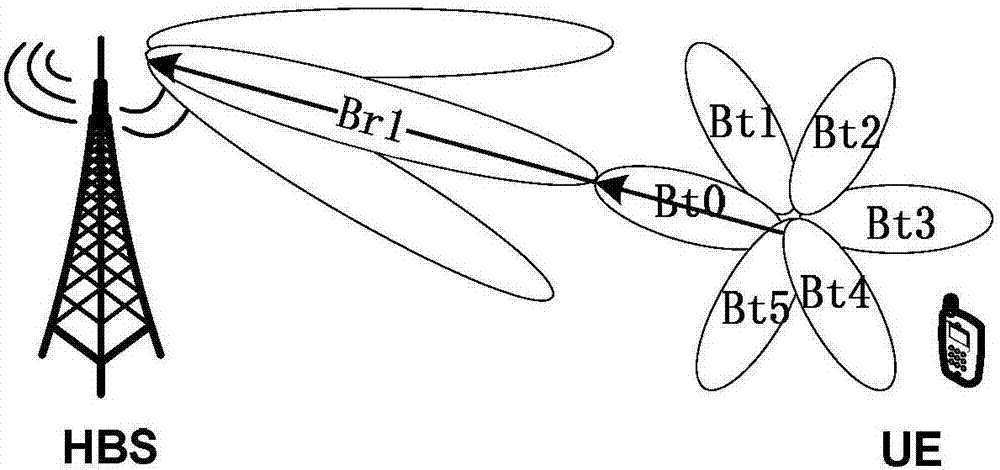
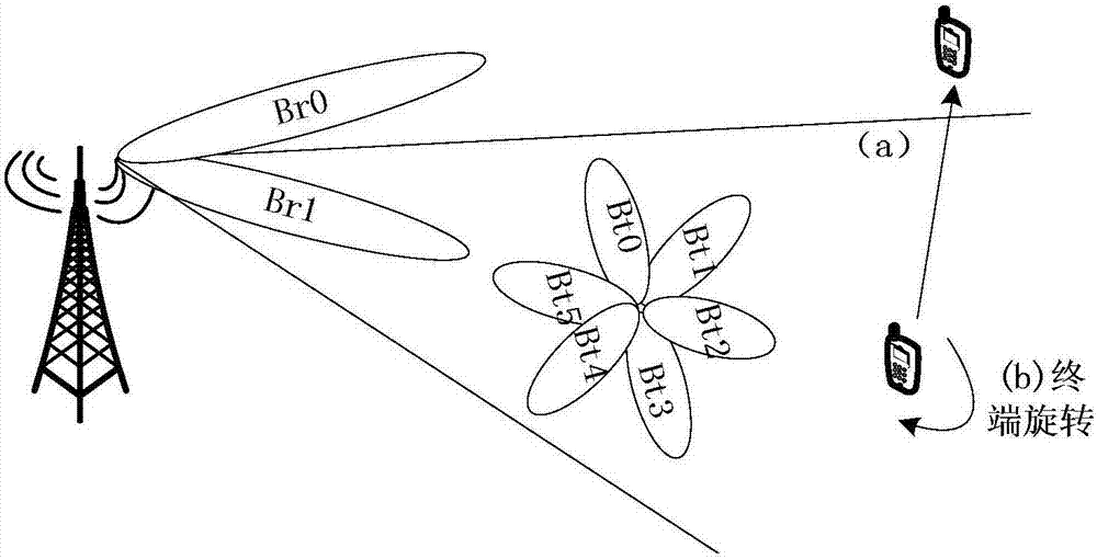
[0181] Such as Figure 8 As shown, this example is for the case where the terminal rotates, that is, the original UE side uplink preferred transmit beam is Bt0, due to the rotation, the uplink preferred transmit beam has changed, the signaling process of the uplink beam tracking method is as follows Figure 9 As shown, the detailed description is as follows:

[0182] Step 1: The UE transmits uplink service data on the time-frequency resources given by the uplink grant (UL grant) through the preferred uplink transmit beam Bt0, and correspondingly, the HBS receives the uplink preferred receive beam Br0.

[0183] Figure 10 It is a schematic diagram of the flow sequence of this example, and a subframe (subframe) marked with an uplink grant indicates that the subframe contains the uplink grant information. Similarly, subsequent subframes marked with uplink service data (UL data), ACK / NACK, uplink beam tracking signal, preferred beam feedback, etc., respectively indicate that the...


PUM


Abstract

The invention discloses an uplink beam tracking method and a corresponding terminal and base station. The terminal sends uplink information to the base station based on an uplink optimized transmitting beam and receives feedback information of the base station, wherein the feedback information is used for indicating a triggering state of uplink beam tracking to the terminal; and when determining that the uplink beam tracking is triggered according to the feedback information, the terminal sends an uplink beam tracking signal to the base station. The base station receives the uplink information sent by a receiving end based on uplink optimized receiving beam, and the base station determines whether to trigger the uplink beam tracking or not according to a receiving state of the uplink information and sends the feedback information to the terminal. According to the scheme, the change state of the uplink optimized transmitting beam can be effectively discovered, and the related uplink beam tracking can be triggered timely.

Description

technical field [0001] The present invention relates to high-frequency communication, in particular to an uplink beam tracking method in high-frequency communication and a corresponding terminal and base station. Background technique [0002] With the continuous advancement of radio technology, a large number of various radio services have emerged, and the spectrum resources on which radio services rely are limited. Facing the continuous increase in people's demand for bandwidth, traditional commercial communications mainly use 300MHz~3GHz The spectrum resources among them are extremely tense, which can no longer meet the needs of future wireless communications. [0003] In the future wireless communication, carrier frequencies higher than those used in the fourth generation (4G) communication system will be used for communication, such as 28GHz, 45GHz, etc. This high-frequency channel has a large free propagation loss, The shortcomings of being easily absorbed by oxygen an...

Claims


Application Information

Patent Timeline
Patent Type & Authority Applications(China)
IPC IPC(8): H04B7/0408H04B7/06
CPCH04B7/0408H04B7/0617H04B7/0636H04B7/04
Inventor 刘星刘文豪毕峰
Owner ZTE CORP
Why Eureka
Try Eureka