Ore breaking device for smelting
A technology of ore crushing and pushing device, which is applied in cleaning methods and appliances, dust removal, grain processing, etc. It can solve problems affecting quality, uneven crushing, complicated operation, etc., and achieve comprehensive crushing and good crushing effect.
- Summary
- Abstract
- Description
- Claims
- Application Information
AI Technical Summary
Problems solved by technology
Method used
Image
Examples
Embodiment 1
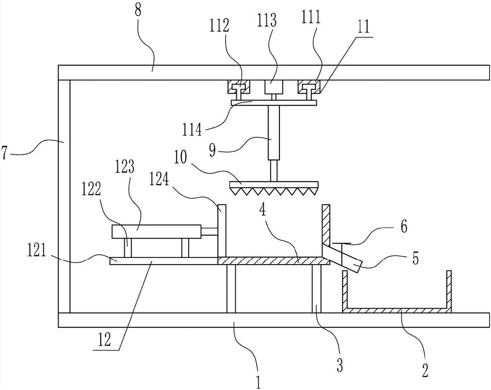
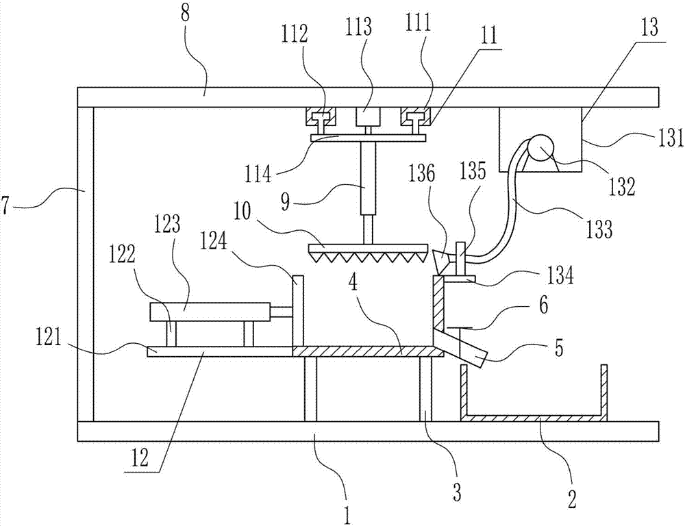
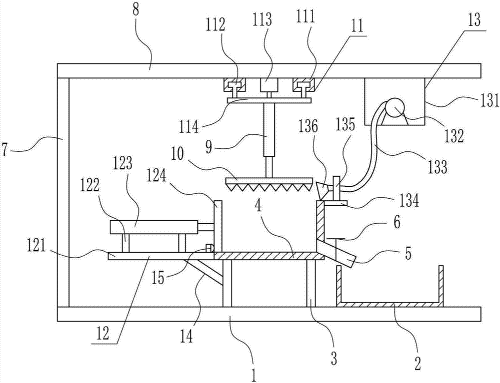
[0027] An ore crushing device for smelting, such as Figure 1-3As shown, it includes a bottom plate 1, a collection frame 2, a support rod 3, a crushing frame 4, a discharge pipe 5, a valve 6, a support plate 7, a top plate 8, a first cylinder 9, a crushing plate 10, a rotating device 11 and a pushing device 12. The support rod 3 is installed symmetrically in the middle of the top of the bottom plate 1 through bolt connection. The crushing frame 4 is installed on the top of the support rod 3 through bolt connection. The lower right side of the crushing frame 4 is connected with the discharge pipe 5. The pipe 5 communicates with the crushing frame 4, and the discharge pipe 5 is arranged obliquely. The valve 6 is arranged on the discharge pipe 5, and the pushing device 12 is arranged on the left side of the crushing frame 4. The pushing parts of the pushing device 12 and the crushing frame 4 contacts, the top right side of the bottom plate 1 is connected by bolts to install the ...
Embodiment 2
[0029] An ore crushing device for smelting, such as Figure 1-3 As shown, it includes a bottom plate 1, a collection frame 2, a support rod 3, a crushing frame 4, a discharge pipe 5, a valve 6, a support plate 7, a top plate 8, a first cylinder 9, a crushing plate 10, a rotating device 11 and a pushing device 12. The support rod 3 is installed symmetrically in the middle of the top of the bottom plate 1 through bolt connection. The crushing frame 4 is installed on the top of the support rod 3 through bolt connection. The lower right side of the crushing frame 4 is connected with the discharge pipe 5. The pipe 5 communicates with the crushing frame 4, and the discharge pipe 5 is arranged obliquely. The valve 6 is arranged on the discharge pipe 5, and the pushing device 12 is arranged on the left side of the crushing frame 4. The pushing parts of the pushing device 12 and the crushing frame 4 contacts, the top right side of the bottom plate 1 is connected by bolts to install the...
Embodiment 3
[0032] An ore crushing device for smelting, such as Figure 1-3 As shown, it includes a bottom plate 1, a collection frame 2, a support rod 3, a crushing frame 4, a discharge pipe 5, a valve 6, a support plate 7, a top plate 8, a first cylinder 9, a crushing plate 10, a rotating device 11 and a pushing device 12. The support rod 3 is installed symmetrically in the middle of the top of the bottom plate 1 through bolt connection. The crushing frame 4 is installed on the top of the support rod 3 through bolt connection. The lower right side of the crushing frame 4 is connected with the discharge pipe 5. The pipe 5 communicates with the crushing frame 4, and the discharge pipe 5 is arranged obliquely. The valve 6 is arranged on the discharge pipe 5, and the pushing device 12 is arranged on the left side of the crushing frame 4. The pushing parts of the pushing device 12 and the crushing frame 4 contacts, the top right side of the bottom plate 1 is connected by bolts to install the...
PUM
 Abstract
Description
Claims
Application Information
 - R&D
- Intellectual Property
- Life Sciences
- Materials
- Tech Scout
- Unparalleled Data Quality
- Higher Quality Content
- 60% Fewer Hallucinations
Browse by: Latest US Patents, China's latest patents, Technical Efficacy Thesaurus, Application Domain, Technology Topic, Popular Technical Reports.
© 2025 PatSnap. All rights reserved.Legal|Privacy policy|Modern Slavery Act Transparency Statement|Sitemap|About US| Contact US: help@patsnap.com


