Solar charging pile device

A charging pile and solar energy technology, which is applied in the field of new energy vehicle charging equipment, can solve problems such as accelerated aging of power supply lines, air pollution, and damage to power supply lines, and achieve the effects of improving utilization efficiency, prolonging service life, and preventing damage

Active Publication Date: 2017-09-08
NANTONG EOPPLY NEW ENERGY ELECTRIC CO LTD
View PDF6 Cites 35 Cited by
  • Summary
  • Abstract
  • Description
  • Claims
  • Application Information

AI Technical Summary

Problems solved by technology

[0002] With the continuous development of the economy, the number of cars continues to increase. Cars are generally powered by gasoline, and the components of gasoline after combustion can pollute the atmosphere, making the problem of air pollution more and more serious. However, with people's awareness of environmental protection With the increase of people's attention to new energy vehicles, pure electric vehicles have become the main force of new energy vehicles. Pure electric vehicles do not need gasoline and diesel, so they have almost no pollution to the atmosphere. The power of pure electric vehicles comes from batteries. , and the battery needs to be charged before it can provide power to the car. Charging is generally completed on the charging pile. On the traditional charging pile, the power supply line is generally of fixed length and will be exposed outside, which is easy to accelerate the aging of the power supply line. Moreover, the power supply line is generally long, so it will hang on the ground. When charging, the power supply line is dragged from the ground, which is easy to cause damage to the power supply line. The charging gun is generally not fixed, and it is easy to fall if it is accidentally touched. Damage occurs on the ground, therefore, there are many disadvantages of traditional charging piles

Method used


Image

  • Solar charging pile device
  • Solar charging pile device
  • Solar charging pile device

Examples


Embodiment Construction

[0020] All features disclosed in this specification, or steps in all methods or processes disclosed, may be combined in any manner, except for mutually exclusive features and / or steps.

[0021] Any feature disclosed in this specification (including any appended claims, abstract and drawings), unless expressly stated otherwise, may be replaced by alternative features which are equivalent or serve a similar purpose. That is, unless expressly stated otherwise, each feature is one example only of a series of equivalent or similar features.

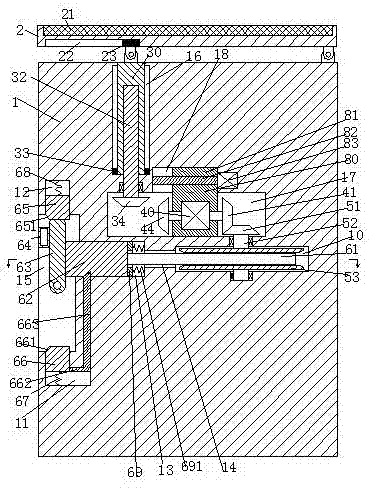
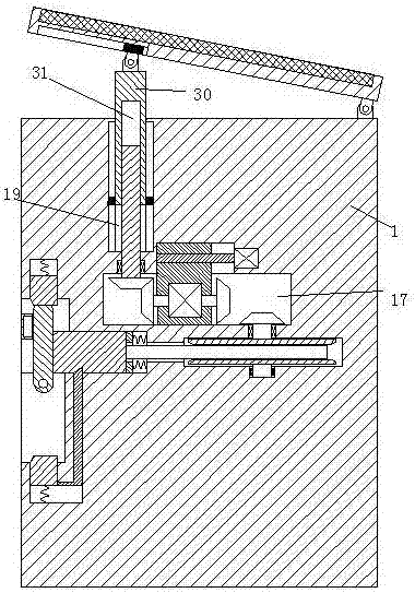
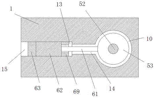
[0022] Such as Figure 1-3 As shown, a solar charging pile device of the present invention includes a charging pile body 1, and the charging pile body 1 is provided with a rotating groove 10, a telescopic groove 13 and a connecting groove 14, and the connecting groove 14 communicates with the rotating groove 10 and telescopic slot 13, the left end surface of the charging pile body 1 is provided with an operation slot 15 extending up and down ...


PUM


Abstract

Disclosed is a solar charging pile device. The solar charging pile device comprises a charging pile, a rotating groove, a telescopic groove and a communicating groove are formed in the charging pile, the rotating groove is communicated with the telescopic groove through the communicating groove, an operation groove which extends up and down and is communicated with the telescopic groove is formed in the left end face of the charging pile, a winding-back disc is rotatably installed in the rotating groove through a rotating shaft, the winding-back disc is wound with a charging line, the charging line penetrates through the communicating groove and extends into the telescopic groove, and a charging gun is fixedly installed at the tail end of the charging line and installed on in the telescopic groove in a sliding mode; the portion, above the rotating groove, in the charging pile is provided with a mounting groove, the upper end wall of the mounting groove is further provided with a guide groove, and a sliding frame is installed in the mounting groove in a left-right sliding mode; a fixed plate is installed at the right upper end of the charging pile in a hinged mode, a photovoltaic panel is fixedly installed on the upper end face of the fixed plate, a lifting adjustment component is further installed at the lower end of the photovoltaic panel, the lower end of the telescopic groove is provided with a locking device for locking the charging gun, and the operation groove is provided with an unlocking device for unlocking the charging gun.

Description

technical field [0001] The invention relates to the field of new energy vehicle charging equipment, in particular to a solar charging pile device. Background technique [0002] With the continuous development of the economy, the number of cars continues to increase. Cars are generally powered by gasoline, and the components of gasoline after combustion can pollute the atmosphere, making the problem of air pollution more and more serious. However, with people's awareness of environmental protection With the increase of people's attention to new energy vehicles, pure electric vehicles have become the main force of new energy vehicles. Pure electric vehicles do not need gasoline and diesel, so they have almost no pollution to the atmosphere. The power of pure electric vehicles comes from batteries. , and the battery needs to be charged before it can provide power to the car. Charging is generally completed on the charging pile. On the traditional charging pile, the power supply...

Claims


Application Information

Patent Timeline
Patent Type & Authority Applications(China)
IPC IPC(8): B60L11/18H01R13/72H02S20/32
CPCB60L53/31B60L53/51H01R13/72H02S20/32Y02E10/50Y02T10/70Y02T10/7072Y02T90/12
Inventor 吴敏杰
Owner NANTONG EOPPLY NEW ENERGY ELECTRIC CO LTD
Why Eureka
Try Eureka